Yaskawa 1000 Series Drive Option - Profibus-DP Technical Manual User Manual
Page 22
7 Option Data and I/O Maps
22
YASKAWA ELECTRIC SIEP C730600 42B 1000-Series Option SI-P3 Technical Manual
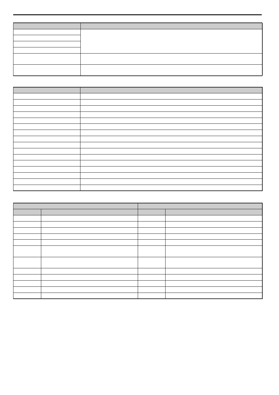
Table 12 Drive Status: U1-12
Table 13 Extended Data 2 Register Map
A
Reserved
B
C
D
E
Fault Trace and Fault History Reset
1: Fault information is reset by the rising edge of this bit.
F
Baseblock command
1: Ext Baseblock
Drive Status
Description
0
1: During run
1
1: During zero speed
2
1: During reverse run
3
1: During fault reset signal input
4
1: During speed agree
5
1: Drive ready
6
1: Alarm
7
1: Fault
8
1: During operation error (oPE)
9
1: During momentary power loss
A
1: NetCtrl status
B
1: M1-M2 relay closed
C
1: Photocoupler output 1 closed
D
1: Photocoupler output 2 closed
E
1: Motor 2 selected
F
1: Zero Servo Complete
Output (Master Device to Drive)
Input (Drive to Master Device)
Byte
<1> Unit depends on the setting of o1-03 (Digital Operator Display Scaling). When the drive is operating in V/f Control or OLV/PM, the drive
output frequency becomes the input data.
Description
Byte
Description
0
Operation Command High Byte
0
Drive Status High Byte
1
Operation Command Low Byte
1
Drive Status Low Byte
2
Frequency Reference High Byte
2
Motor Speed High Byte
3
Frequency Reference Low Byte
3
Motor Speed Low Byte
4
MEMOBUS/Modbus Function Code
4
MEMOBUS/Modbus Function Code
5
MEMOBUS/Modbus Starting Register Address High
Byte
5
MEMOBUS/Modbus Starting Register Address High
Byte
6
MEMOBUS/Modbus Starting Register Address Low
Byte
6
MEMOBUS/Modbus Starting Register Address Low
Byte
7
MEMOBUS/Modbus Data Length
7
MEMOBUS/Modbus Data Length
8
MEMOBUS/Modbus Data 1 High Byte
8
MEMOBUS/Modbus Data 1 High Byte
9
MEMOBUS/Modbus Data 1 Low Byte
9
MEMOBUS/Modbus Data 1 Low Byte
10
Reserved
10
Reserved
11
Handshaking Register
11
Handshaking Register
Command Signal
Description