Modified parameters, 4 related parameters and functions – Yaskawa AC Drive - A1000 Motion Control Custom User Manual
Page 11
4 Related Parameters and Functions
YASKAWA TM.A1000SW.117 Motion Control Custom Software Supplement
11
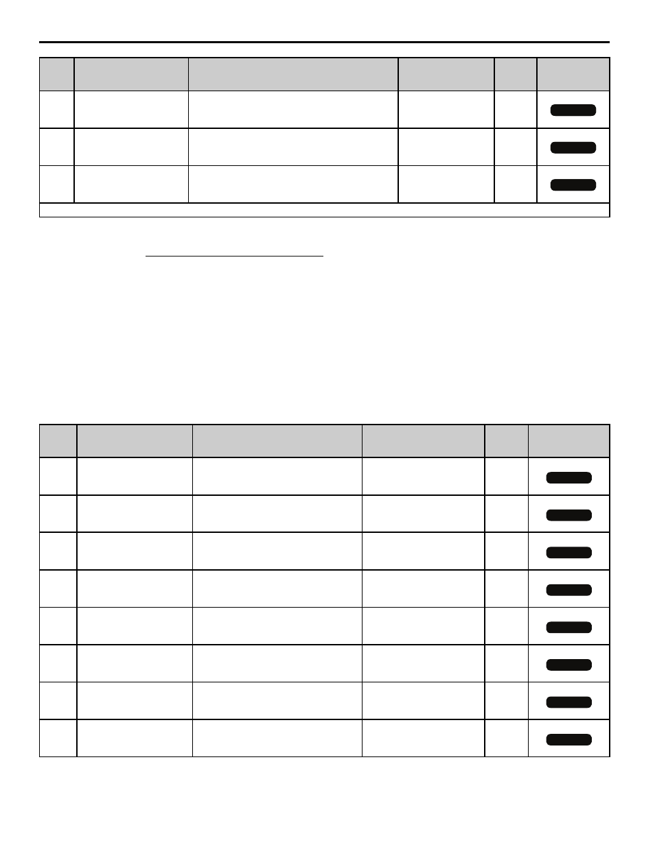
Modified Parameters
Table 3 Modified Parameters
P4-14
(62Dh)
Position 14
Position 14
Position Reference in units. Position Ref.
(counts)=P4-14 × P1-09
Default: 0.00
Range: 655.35
Units
Yes
P4-15
(62Eh)
Position 15
Position 15
Position Reference in units. Position Ref.
(counts)=P4-15 × P1-09
Default: 0.00
Range: 655.35
Units
Yes
P4-16
(62Fh)
Position 16
Position 16
Position Reference in units. Position Ref.
(counts)=P4-16 × P1-09
Default: 0.00
Range: 655.35
Units
Yes
<1> The actual command destination is calculated as follows when P1-02=3: Destination=Memobus register 6D1h × P1-09/100.
<2> Actual destination (in encoder quadrature counts) is calculated as follows:
<3> The actual commanded destination is the combined value of Memobus registers 6D0h (low word) and 6D1h (high word) when P1-02 = 3.
Parameter P1-09 has no effect as this is strictly a command in encoder quadrature counts. Speed for this profile is set by d1-01, the acceleration
time is set by C1-01, and the deceleration time is set by C1-02.
<4> The units text displayed in the digital operator are determined by parameter P1-10. Actual destination in encoder counts is calculated by
multiplying the preset position reference by P1-09.
<5> When parameter P3-01=3 or 4 (encoder type = absolute incremental), the Homing Type (P2-01) parameter has no effect. The drive is base-
blocked and then the position is read from the encoder via the PG-X3 card installed in CN5-B when a home command is issued. This will only
happen if the drive does not have a run command.
<6> The position reference is lower-limited to 0 counts and upper-limited to 262143 counts with a Gray Encoder.
<7> Parameter F1-31 is ignored by the Motion Control software. It uses parameter P3-02 instead.
<8> If P3-01 = 1, then parameter P3-02 is used in place of parameter F1-01 when determining actual distance.
No.
(Addr.
Hex)
Parameter Name
Digital Operator Display
Description
Values
Change
During
Run
Control Mode
Access Level
C1-01
(200h)
Acceleration Time 1
Accel Time 1
Sets the time to accelerate from 0 to
maximum frequency.
Default: 2.0 s
Range: 0.0 to 6000.0 s
Yes
C1-02
(201h)
Deceleration Time 1
Decel Time 1
Sets the time to decelerate from maximum
frequency to 0.
Default: 2.0 s
Range: 0.0 to 6000.0 s
Yes
C1-03
(202h)
Acceleration Time 2
Accel Time 2
Sets the time to accelerate from 0 to
maximum frequency.
Default: 2.0 s
Range: 0.0 to 6000.0 s
No
C1-04
(203h)
Deceleration Time 2
Decel Time 2
Sets the time to decelerate from maximum
frequency to 0.
Default: 2.0 s
Range: 0.0 to 6000.0 s
Yes
C1-05
(204h)
Acceleration Time 3
(Motor 2 Accel Time 1)
Accel Time 3
Sets the time to accelerate from 0 to
maximum frequency during Motor 2
operation.
Default: 2.0 s
Range: 0.0 to 6000.0 s
Yes
C1-06
(205h)
Deceleration Time 3
(Motor 2 Decel Time 1)
Decel Time 3
Sets the time to decelerate from maximum
frequency to 0 during Motor 2 operation.
Default: 2.0 s
Range: 0.0 to 6000.0 s
Yes
C1-07
(206h)
Acceleration Time 4
(Motor 2 Accel Time 2)
Accel Time 4
Sets the time to accelerate from 0 to
maximum frequency during Motor 2
operation.
Default: 2.0 s
Range: 0.0 to 6000.0 s
Yes
C1-08
(207h)
Deceleration Time 4
(Motor 2 Decel Time 2)
Decel Time 4
Sets the time to decelerate from maximum
frequency to 0 during Motor 2 operation.
Default: 2.0 s
Range: 0.0 to 6000.0 s
Yes
No.
(Addr.
Hex)
Parameter Name
Digital Operator Display
Description
Values
Change
During
Run
Control Mode
Access Level
OLV
CLV
OLV
CLV
OLV
CLV
Destination =
Frequency Reference (hi-speed rgister)
100
P1-09
X
All Modes
All Modes
All Modes
All Modes
All Modes
All Modes
All Modes
All Modes