Yaskawa AC Drive - A1000 Motion Control Custom User Manual
Page 23
5 Function Description
YASKAWA TM.A1000SW.117 Motion Control Custom Software Supplement
23
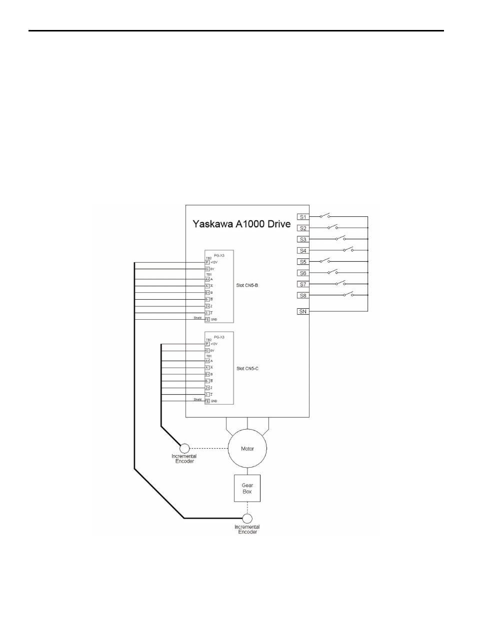
Dual Incremental Encoders
The encoder used for position is mounted elsewhere on the machine. The need for a positive drive setup is somewhat
reduced using this scheme. A second motor-mounted encoder is required for optimum performance. The ratio between
the motor and the machine-mounted encoder needs to be entered into parameters P3-03 and P3-04, and the PPR of the
encoder needs to be entered into P3-02. Note that parameter F1-31 is ignored in the Motion Control software. The gear
ratio numerator (P3-03) and denominator
Parameter P3-04 is relative to the positioning axis (machine mounted encoder), not the motor. For example, if the motor is
connected to the axis where the positioning encoder is mounted via a 2:1 gearbox (meaning, for every 2 rotations of the
motor shaft, the secondary positioning encoder turns 1 rotation), P3-03 should be set to 1 and P3-04 should be set to 2.
This configuration requires a second PG-X3 or PG-B3 card installed in the CN5-B option card slot.
Note: Wiring between for the encoder marker pulse (Z+ and Z-) is only required if using a Homing w/marker homing routine
(P2-01 = 4 or 5).
Figure 5
Figure 5 Dual Incremental Encoder Wiring (P3-01=1)