4 related parameters and functions, Control modes, symbols and terms, Additional parameters and modified parameters – Yaskawa AC Drive - A1000 Motion Control Custom User Manual
Page 8: Related parameters and functions, 4related parameters and functions, Additional parameters
8
YASKAWA TM.A1000SW.117 Motion Control Custom Software Supplement
4 Related Parameters and Functions
4
Related Parameters and Functions
Control Modes, Symbols and Terms
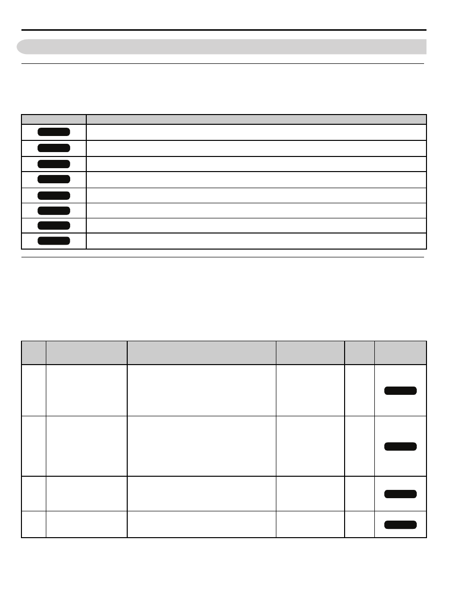
The table below lists terms and symbols used in this section to indicate which parameters are available in which control
modes.
Additional Parameters and Modified Parameters
Additional Parameters
are used to set up the drive for operation with the software. Parameters are available in the
control modes shown in the Description column. The only valid Control Mode Access Level for the listed parameters in
is CLV (Closed Loop Vector).
Table 2 Additional Parameters
Description
Parameter is available in all control modes.
Parameter is available when operating the drive with V/f Control.
Parameter is available when operating the drive with V/f with PG Control.
Parameter is available when operating the drive with Open Loop Vector.
Parameter is available when operating the drive with Closed Loop Vector.
Parameter is available when operating the drive with Open Loop Vector for PM monitors.
Parameter is available when operating the drive with Advanced Open Loop Vector for PM monitors.
Parameter is available when operating the drive with Closed Loop Vector for PM monitors.
No.
(Addr.
Hex)
Parameter Name
Digital Operator Display
Description
Values
Change
During
Run
Control Mode
Access Level
P1-01
(600h)
Motion Type
Motion Type
0: Disabled
1: Linear Absolute
2: Rotary Absolute
3: Relative Mem Off
4: Relative Mem On
Default: 0
Range: 0 to 4
No
P1-02
(601h)
Distance Select
Distance Select
0: Preset P4-
1: Modbus 16 Bit (06D0h and 06D1h)
2: Option Card
Hi-Speed Option Card Frequency Reference
Register
A multifunction input selection of
Distance Select will override this parameter.
3: Modbus 32-Bit (06D0h and 06D1h)
Default: 0
Range: 0 to 3
No
P1-03
(602h)
Move Command Type
Move CMD. Type
0: Maintained-Move command must be maintained
for the entire move.
1: Rising Edge-Move command is edge-triggered.
2: Falling Edge-Move command is edge-triggered.
Default: 0
Range: 0 to 2
No
P1-04
(603h)
Positioning proportional
Gain
Pos P Gain
Proportional gain used for the position controller.
Default: 1.0
Range: 1.0 to 20.0
Yes
All Modes
V/f
V/f
V/f w PG
V/f w PG
OLV
OLV
OLV
OLV
OLV
CLV
V/f w PG
OLV/PM
V/f w PG
AOLV/PM
CLV/PM
OLV
CLV
OLV
CLV
OLV
CLV
OLV
CLV