Motion and velocity profile, 5 function description – Yaskawa AC Drive - A1000 Motion Control Custom User Manual
Page 27
5 Function Description
YASKAWA TM.A1000SW.117 Motion Control Custom Software Supplement
27
Motion and Velocity Profile
Command Position
The commanded position is determined by the multi-function inputs and by the setting of parameter P1-02.
Move Velocity
The speed of the move is determined by one of the d1 parameters, as shown in
on page
to perform a trapezoidal move. If, due to the accel and decel rates, move velocity and commanded position, the drive
cannot reach the full move velocity, the move will be triangular. If an alternate frequency reference or jog is commanded
via multi-function inputs during a move, the drive will run at the new commanded or jog speed until it is no longer
activated, at which time the move will be canceled, and the drive will ramp to zero speed. The position is tracked when
operating at an alternate commanded frequency reference or in local mode. If the internal register that tracks position (or
position + home offset) exceeds 10
9
encoder counts, the drive/machine will need to be re-homed. If motion control is
disabled (either via parameter P1-01 or the Motion Disable multi-function input), the drive no longer tracks position, and
may need to be re-homed depending on encoder type and move type.
Positioning Routine
When a move is commanded, the drive will accelerate on the selected acceleration ramp up to the commanded move
velocity. During this time the drive is calculating both when to start the deceleration ramp and the optimum positioning
speed, based on the current position, current velocity, selected decel rate, and position regulator gain. When the begin
decel point is reached, the drive’s speed reference will be clamped at the calculated positioning speed and the drive will
decelerate on the selected deceleration ramp. Once the machine speed is at or below the positioning speed the speed will
be completely controlled by the position regulator, with a speed limit of positioning speed. When the machine then enters
the in position window, and the motor speed is below the DC injection start frequency (b2-01) the in position digital
output is activated and the drive seeks to resolve all position error.
A RUN command must be present prior to commanding a move. If the move is commanded before the run command, the
move command is ignored and the drive remains at zero speed. If the RUN command is removed during a move,
parameter b1-03 determines the stopping method. If the stopping method is Ramp To Stop, the decel rate used is the one
selected at the beginning of the move.
The motion and velocity profile is latched in at the beginning of the move. If the position, velocity or accel/decel is
changed during the move, it will be ignored until the next move command is given.
If an absolute move is commanded before the drive has been homed, a warning is displayed: RHS Run Homing Sequence
and the drive remains at zero speed.
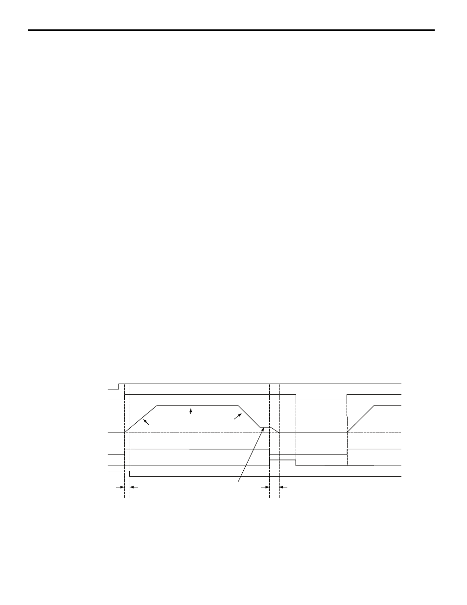
Figure 9
Figure 9 Typical Move Profile From Home to a Positive Position-Maintained Move Command (P3-01=0)
Digital
Inputs
Motor
Speed
Digital
Outputs
Run Cmd
Move Cmd
During Move
Move Complete
At Home
Selected
Accel
Rate
Selected
Decel
Rate
Selected
Max.
Speed
In Position
Window
(P1-08)
In Position
Window
(P1-08)
Positioning
Speed
(Determined
Automatically)
0 Hz
60 Hz