Command position – Yaskawa AC Drive - A1000 Motion Control Custom User Manual
Page 20
5 Function Description
20
YASKAWA TM.A1000SW.117 Motion Control Custom Software Supplement
Relative Motion
Relative motion would be used in applications such as cut-to-length and metering pumps. Can be used with or without a
homing sequence. When the motion type is Relative Mem Off (P1-01 = 3) the move distance is measured from the
position at the time of the move command. When the motion type is Relative Mem On (P1-01 = 4), the distance is
measured from the destination of the previous move. If a conveyor with pockets or flights is being indexed, Relative Mem
On would be the appropriate motion type.
When the motion type is Relative Mem On and a move is interrupted before completing, the drive checks to see if it is
within the In Position Window of its previously commanded destination when a new move is commanded. As an example,
consider a commanded move distance of 5.00 units. If the drive moves 2.00 units before the move is interrupted, it then
checks to see if it’s within the in position window of its destination of 5.00 units. If it has not yet reached the in position
window and another move command is given, the drive will move 3.00 units from its current position to complete its
original move of 5.00 units. If the in position window is set large enough that the drive was within this window when it
stopped at 2.00 units, the next time a move command is given, the drive will move a total of 8.00 units – 3.00 units to
complete its original move plus 5.00 units for the newly commanded move.
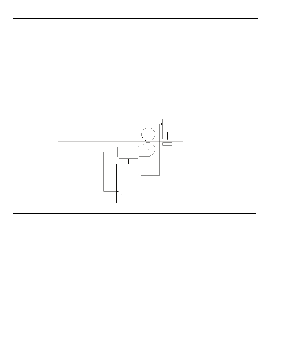
Figure 3
Figure 3 Relative Motion Example - Cut to Length
Command Position
Digital Preset
Up to 16 different digital preset positions can be programmed. Each position is set in user selectable units, set up by
parameters P1-09 and P1-10. Distance in encoder counts can be calculated by multiplying the digital preset value by
parameter P1-09 (counts per rev). Encoder counts refers to the counts after quadrature. The counts after quadrature is
typically four times that of the Pulses Per Revolution rating of all compatible encoders except the absolute gray code type.
Encoder counts are not multiplied by 4 for the gray code type of encoder. Move velocity is determined by a different
parameter for each digital preset position. Accel and decel rates will be one of four different sets as shown in
Memobus Distance
One 16 bit Memobus register is used to command a speed during a move, and one 16 bit Memobus register is used to
command a position. Memobus register 06D0h holds the speed reference (in 0.01 Hz), and register 06D1h holds the
position reference in engineering units. These registers can be written to using the drive’s built-in Memobus
communications, or by other optional protocols such as DeviceNet, Ethernet or Profibus. Accel and decel rates are
determined by parameters C1-01 and C1-02.
Option PCB (Frequency Reference) Register
In this mode, the drive’s option PCB frequency reference is redefined and used as the commanded distance. The
commanded position originates from the Frequency Reference channel of the option board.
PG-X3
Move
Complete
Yaskawa
A1000 Drive
Gear
Box
Shear
Encoder
Motor