Magnum Energy AC Load Diversion Controller (ACLD-40) User Manual
Page 17
©
2015 Sensata Technologies
Page 10
Installation
2.2 Locating the ACLD Controller
Only install the ACLD controller in a location that meets the following requirements:
Clean and Dry – The controller should not be installed in an area that allows dust, fumes, insects,
or rodents to enter or block the controller’s ventilation openings. This area also must be free from
any risk of condensation, water, or any other liquid that can enter or fall on the controller. Failure
due to any of the above conditions is not covered under warranty.
Info: If the controller is installed in an area where moisture may occur, we recommend
putting silicone dielectric grease compound into the electrical ports (as shown in Figure
1-3, Items 2 and 3). Before installing the cables, or if leaving any ports open, squirt a
liberal amount into each port. Silicone dielectric compound makes an
effective moisture
and corrosive barrier to help protect and prevent corrosion to the RJ11 connections.
Cool – The controller should be protected from direct sun exposure or equipment that produces
extreme heat. If the ambient temperature around the controller exceeds 77°F (25°C), the power
specifi cations are reduced.
Ventilation – In order for the controller to provide full output power and to avoid over-temperature
fault conditions, do not cover or block the controller’s ventilation openings or install this controller
in an area with limited airfl ow. The controller uses a fan to provide forced air cooling, this fan pulls
in air through the intake opening (see Figure 1-3, Item 5) and blows out air through the exhaust
vents (see Figure 1-4, Item 7). Allow at the minimum an airspace clearance of 6” (15.2 cm) at
the intake and exhaust vents, and 3” (7.6 cm) everywhere else to provide adequate ventilation.
Safe – Keep any fl ammable/combustible material (i.e., paper, cloth, plastic, etc.) that may be
ignited by heat, sparks, or fl ames at a minimum distance of 2 feet (61 cm) from the controller.
Have access to the MS-PAE Series inverter – The communications control for the ACLD is provided
by the MS-PAE Series inverter, so the ACLD controller must be in an area that allows the network
cable to be connected to the inverter. The network cable provided is 6’ and can be extended up to a
length of 200 feet without data degradation. See Section 2.10.1 for more information on the cable.
Accessible – Do not block access to the controller’s inverter and network ports, as well as the
ON/OFF switch and status indicator. Allow enough room to access the AC wiring terminals and
connections, as they will need to be checked and tightened periodically.
Away from sensitive electronic equipment – High powered devices with PWM circuitry can
generate levels of RFI (Radio Frequency Interference). Locate any electronic equipment susceptible
to radio frequency and electromagnetic interference as far from the controller as possible.
2.2.1 Conduit
Knockouts
The ACLD controller
comes standard with four dual knockouts (for 1/2” and 3/4” conduits) on each
side (eight total). Figure
1-3 shows the location of these conduit knockouts.
Select the appropriate
knockout that is close to the terminal that the wire will connect to, or whichever one works for the
way your fi eld wiring comes in.
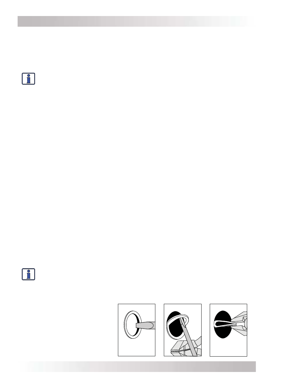
Info: The knockouts can be easily removed by tapping the edge with a straight bladed
screwdriver and a hammer, then
twist out with pliers. See Figure 2-2.
Before removing any knockouts and mounting the ACLD controller, think about whether you are
going to use
cable clamps or conduit (using the optional MPX-CB conduit box), and
the different
wiring required. See Section 2.4.3 for wire routing requirements to/from the ACLD controller.
Figure 2-2, Removing
Knockouts