Magnum Energy AC Load Diversion Controller (ACLD-40) User Manual
Page 21
©
2015 Sensata Technologies
Page 14
Installation
2.4.4
Wire Size and Overcurrent Protection
The wiring must be approved for the application (i.e., residential wiring) and sized per the local
electrical safety code requirements to ensure the wire’s ability to safely handle the maximum load
current. The wiring must be protected from short circuits and overloads by an overcurrent protection
device. This overcurrent protection device must have a means to disconnect the circuits (e.g., circuit
breaker or a fuse/disconnect), be properly sized, and branch circuit rated for the wire it is protecting.
As shown in Figure 2-5, the ACLD provides two input circuits, the Battery Based Inverter (BBI)
and Grid-Tie Inverter (GTI) input circuits. As part of the installation, overcurrent protection rated
to handle a maximum 30 amps must be provided from the source to these two input circuits. A
dual-pole, 30 amp, 240-volt branch rated circuit breaker to protect both L1 and L2 circuits for
each input circuit is required. Referring to Figure 2-6, the BBI input to the ACLD (terminals 1 and
2) is protected from a 30A breaker from the main utility panel; and the GTI input to the ACLD
(terminals 5 and 6) is protected using the 30A breaker in the MMP. Note: If the MMP enclosure is
not used, an external panel with a 30A breaker must be provided to protect the GTI input from
the Grid-Tie Inverter.
The ACLD also provides a primary output circuit (terminals 7 and 8) and secondary output circuit
(terminals 9 and 10) that are connected to the diversion loads. An external overcurrent protection
device is not required for these two output circuits as the diversion loads are the only connections
to these two circuits and these circuits are protected by the ACLD’s internal electronic overcurrent
protection circuitry.
CAUTION: The ACLD internal wires are rated for 30 amps, the pass-thru current must
be no greater than 30 amps or damage to the ACLD will occur.
CAUTION: The wiring must be no less than #10 AWG (5.3 mm
2
) gauge copper wire
and be approved for the application (i.e., residential wiring).
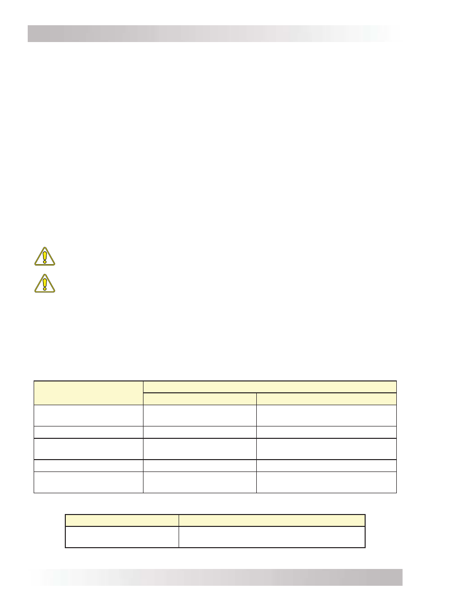
2.5 Torque
Requirements
Follow the specifi c torque recommendations below to ensure your fasteners are tightened
suffi ciently. To ensure your connections are correct, you should use an accurate, quality torque
wrench. It is highly recommended to go back over all fasteners and re-torque after fi ve days, and
every six months thereafter.
Table 2-1, Torque Values for Ground Busbar
Note: The ground busbar has different torque values for the small and large screws.
Wire Size
Busbar Screw Size Torque Values
10-32 [Small Screw]
5/16-24 [Large Screw]
#14 to #10 AWG
(2.1 to 5.3 mm
2
)
15 in. lbs. (1.7 N-m)
35 in. lbs. (4.0 N-m)
#8 AWG (8.4 mm
2
)
20 in. lbs. (2.3 N-m)
40 in. lbs. (4.5 N-m)
#6 AWG
(13.4 mm
2
)
25 in. lbs. (2.8 N-m)
45 in. lbs. (5.1 N-m)
#4 AWG (21.1 mm
2
)
NA
45 in. lbs. (5.1 N-m)
#3 to #1/0 AWG
(26.6 to 53.5 mm
2
)
NA
50 in. lbs. (5.6 N-m)
Table 2-2, Torque Values for the AC Terminal Blocks
Wire Size
Slotted M3.5 Screw Torque Values
#14 to #6 AWG
(2.1 to 13.4 mm
2
)
16 in. lbs. maximum
(1.8 N-m maximum)