Installation 2.6 acld terminal block connections, 7 electrical system wiring diagrams – Magnum Energy AC Load Diversion Controller (ACLD-40) User Manual
Page 22
Page 15
©
2015 Sensata Technologies
Installation
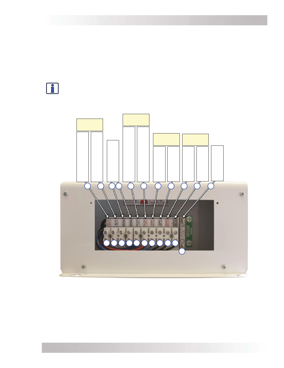
2.6 ACLD Terminal Block Connections
The ACLD controller has a ten-pole terminal block and a ground busbar to permanently connect
the BBI/Battery Based Inverter (e.g., MS-PAE Series), the GTI/Grid-Tie Inverter and any primary
or secondary loads (see Figure 2-5). To access and view the terminal block and ground busbar,
remove the two Phillips screws holding the AC wiring access cover plate (see Figure 1-5, Item 9).
Each connection on the terminal block is rated to accept one #14 to #6 AWG (2.1 to 13.4 mm
2
)
CU stranded wire, or two #12 AWG (3.3 mm
2
) CU stranded wires. Each connection uses a M3.5
slotted head screw, and the maximum tightening torque is 16 in. lbs. (1.8 N-m).
Info: Both of the ACLD’s NEUTRAL terminals are electrically connected to each other
and either connection can be used to connect the inverter and electrical panel.
The ground busbar has two #14 to #1/0 AWG (2.1 to 53.6 mm
2
) and three #14 to #6 AWG (2.1 to
13.4 mm
2
) compression terminals with slotted-head screws. See Table 2-1 for torque requirements.
2.7 Electrical System Wiring Diagrams
A diagram of the wiring for the ACLD controller is shown in Figure 2-6, and is provided to assist
you or your system installer. Due to the variety of applications and differences in local and national
electrical codes, this wiring diagram should be used as a general guideline only. It is not intended
to override or restrict any national or local electrical codes; and, this diagram should not be the
determining factor as to whether the installation is compliant, that is the responsibility of the
electrician and the onsite inspector.
Figure 2-5, ACLD Terminal Block
11
10
9
8
7
6
5
4
3
2
1
11
10
9
8
7
6
5
4
3
2
1
From MS-P
AE Series
in
verter (HO
T 2 out)
From MS-P
AE Series
in
verter (HO
T 1 out)
Common Neutr
als
(from in
verters)
From Sub-P
anel /Grid-
Tie In
verter (LEG 1 out)
From Sub-P
anel /Grid-
Tie In
verter (LEG 2 out)
To
Primary
Load (LEG 2)
To
Secondary
Load (LEG 1)
To
Primary
Load (LEG 1)
To
Secondary
Load (LEG 2)
Ground Busbar (In & Out)
INPUT
(GTI)
INPUT
(BBI)
OUTPUT
(PRI)
OUTPUT
(SEC)