General information, Carrying out measurements connection power supply – Amprobe PQ55A Power-Analyzer User Manual
Page 12
General information
�
The safety references must be followed.
☞
The respective accident prevention regulations established by the professional
associations for electrical systems and equipment must be strictly met at all
times.
Carrying out Measurements
Connection Power Supply
�
The respective accident prevention regulations established by the professional
associations for electrical systems and equipment must be strictly met at all
times.
�
To avoid electric shock, safety measures must be observed when working with
voltages higher than 120 V (60 V) DC or 50 V (25 V) RMS AC. These are the
values of threshold contact voltages given by DIN VDE. The values in brackets
apply to medical and agricultural applications.
�
Measurements in dangerous proximity of electrical installations are only to
be executed when instructed by a responsible electrical specialist, and never
alone.
�
Before connecting the test leads, the measurement instrument must be set to
the correct type of connection.
�
The correct connection assignment for voltage and current must imperatively
be observed.
☞
Phase assignment: The measurement inputs may not be exchanged. I.e. if, for
example, the voltage clips for the first phase are connected to voltage input
U1, the current clamp pertaining to this phase must be connected to current
input I1. Observe the markings of the clamp adapters and the connection
field.
�
Before connecting the test leads, determine the neutral conductor for N input
using an appropriate measurement instrument
�
The test leads and test probes may only be touched at the handles provided
for this purpose. Any direct contact with the test probes must imperatively be
avoided.
�
The measurement inputs U1, U2, and U3 are galvanically connected. Input N
is the common reference point. Measurement inputs which are not required
may not be connected!
�
When using clamp adapters, special care has to be applied that they are con-
nected to a measurement instrument before they surround a live conductor.
Open clamp adapter outputs can be dangerous for the user and can lead to
the destruction of the clamp adapter, caused by high induction voltages.
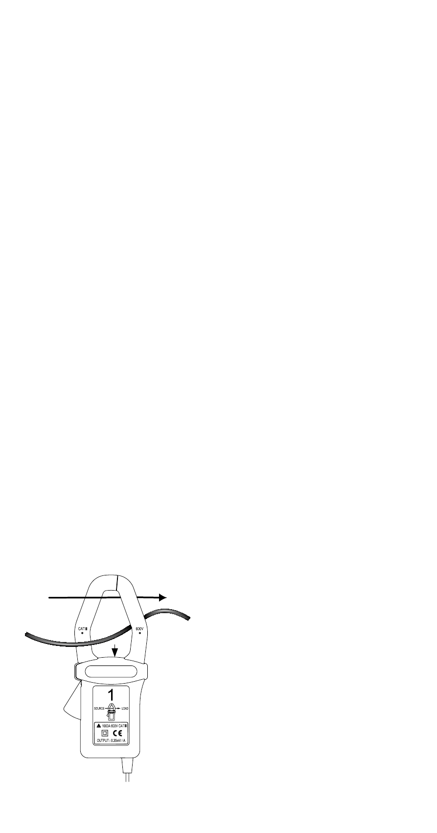
☞
When connecting clamp adapters, special care has to be applied that the
arrow marked on the current clamps (direction of current flow) must point
from the electric power supply to the load. I.e. the printed arrow must point
to the electric power supply.
☞
Shaft direction (X1)
If a clamp is connected in the opposite
direction, the power measured at this
phase would appear to be negative.
☞
As the voltage input U1 represents the
main signal for the Power Analyzer, this
input must always be connected, i.e. even
for measurements of U2, U3, I1, I2, and
I3. If this input is not connected or if no
voltage is present, the measurement instru-
ment will not record any measurement
values.
12
X1