Amprobe PQ55A Power-Analyzer User Manual
Page 8
☞
All keys must be pressed until an acoustic signal is audible.
3.
Lateral connection for electric power supply.
�
The instrument may only
be connected to the mains adapter shipped with the PQ55A or a mains
adapter complying with the data defined within the specification section.
4.
Lateral optically isolated connection for the RS-232 interface
5.
LCD (liquid crystal display)
6.
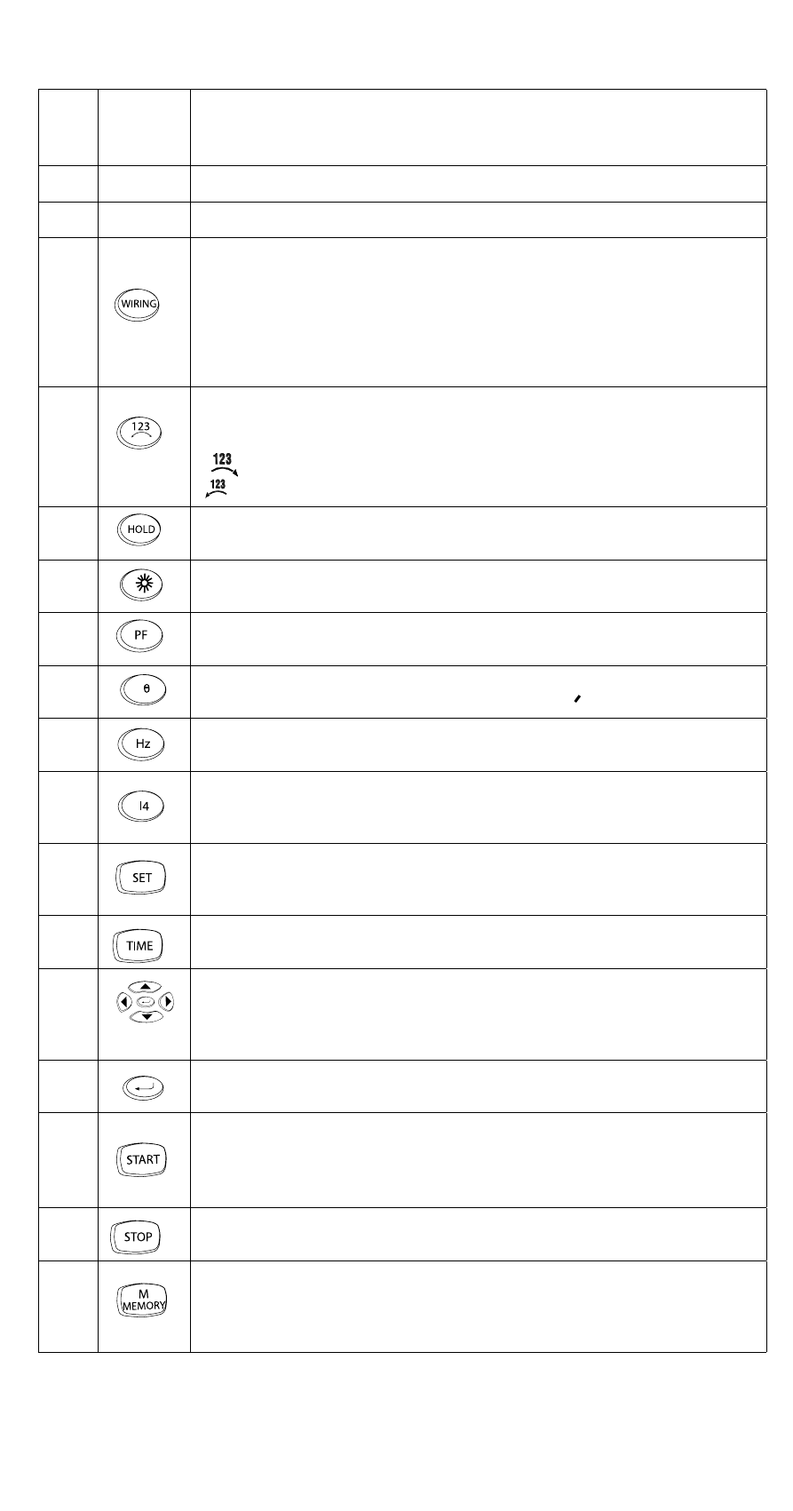
Key for type of connection. Function key to select the type of connection.
Selection can be made among the following type of connections (please
also refer to chapter 5.3.1 Connection to the electric power supply system):
1P2W: ......................single phase power measurement
1P3W: ......................two-phase power measurement
3P3W2M: ..................three-phase power measurement, Aron connection
3P4W: ......................three-phase power measurement, star connection
7.
Key for rotary field determination. The rotary field is determined when
selecting the type of connection “3P4W” by pressing this key and is indi-
cated on the display as follows:
: clockwise rotary field
: counterclockwise rotary field
8.
Key for Data Hold, to hold the display value. If the HOLD function is
activated, the symbol [HOLD] is displayed on the screen.
9.
Key for display illumination (backlight)
The backlight switches off automatically after approx. 30 seconds.
10.
Power factor indication. Key to swtich to the power factor indication. If
the display selection is switched on, the symbol “PF” is indicated.
11.
Phase angle indication. Key to commute to the phase angle indication. If
the display selection is switched on, the symbol “
0
“ is indicated.
12.
Mains frequency indication. Key to commute to the mains frequency dis-
play. If the display selection is switched on, the symbol “Hz” is indicated.
13.
Indication of current measurement via clamp 4. Key to switch to indicate
the current measurement via input “I4”. If the display selection is swit-
ched on, the symbol “I4 A” is indicated.
14.
Time setting. Key used to activate the time setting. Simultaneous pressing
of keys “SET” and “TIME” activates the date and time setting as well as
the sampling rate.
15.
Key used to display the date and time. Reference: This display is automa-
tically switched off after approx. 10 seconds.
16
Navigation keys. Keys used to set the time and to call the memorised
values.
16a.
ENTER key to confirm any setting
17.
Data logger - Key to start the recording of measurement values
☞
If the recording function is activated, the symbol [M] blinking with
the preset measurement rate. Below, the number of the current
series of measurements is displayed.
18.
Dater logger - Key to terminate the recording of measurement values.
19.
Measurement data memory - Key to save individual measurement data.
When saving a measurement, the symbol [M] is briefly displayed on the
screen with the indication of the storage place number below. It is pos-
sible to save up to 99 measurement values.
8