Determining the rotary field – Amprobe PQ55A Power-Analyzer User Manual
Page 24
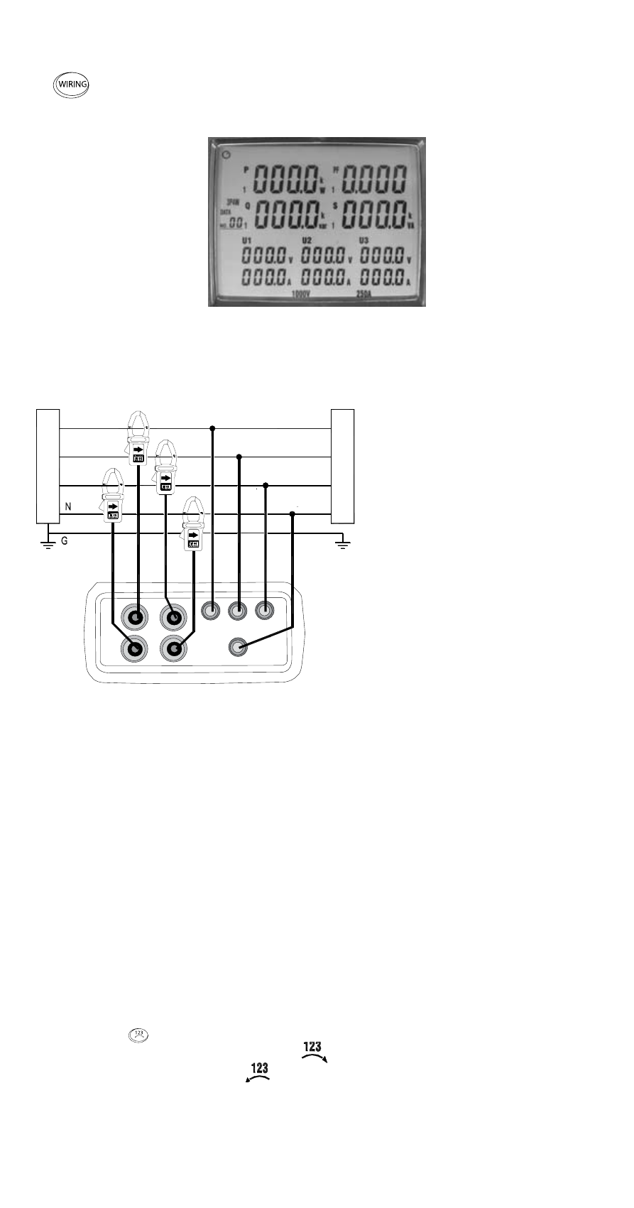
Determining the Rotary Field
1) Switch on the instrument
2)
Select the type of connection 3P4W using the “Wiring” function key
(6). After selection, the following display is indicated with the symbol
3P4W (5.11):
Display Type of connection 3P4W
The measurement inputs are connected as illustrated in the following drawing:
Type of connection 3P4W rotary
field
L1: phase 1
L2: phase 2
L3: phase 3
N: neutral conductor
G: protective earth
Connect the test leads to the measurement instrument as follows:
1) Connect black test lead to socket N.
☞
The connection to the neutral conductor is not required as the rotary field
detection functions even without this connection.
2) Connect red test lead to socket U1.
3) Connect yellow test lead to socket U2.
4) Connect blue test lead to socket U3
5) Now, connect the tests leads to the electric power supply to be tested using
the alligator clips.
6) Connect black test lead to neutral conductor N.
7) Connect red test lead to phase L1.
8) Connect yellow test lead to phase L2.
9) Connect blue test lead to phase L3.
☞
The minimum voltage for the rotory field detection amounts to 30 V.
10) Press the
key.
For clockwise rotary field, the symbol
(5.29) is displayed on the screen.
Counterclockwise rotary field
.
☞
If one or more conductor voltages are missing, an acoustic signal is audible
and the rotary field detection is disabled.
I1
I3
I2
I4
U1
U2
U3
N
CURRENT PROBE
CAT III 600V ALL INPUT
INPUT: 0,35mV/A
0.35V MAX
L1
red
black
Curr
ent Supply
Consumer
yellow
L2
L3
blue
24