Amprobe PQ55A Power-Analyzer User Manual
Page 17
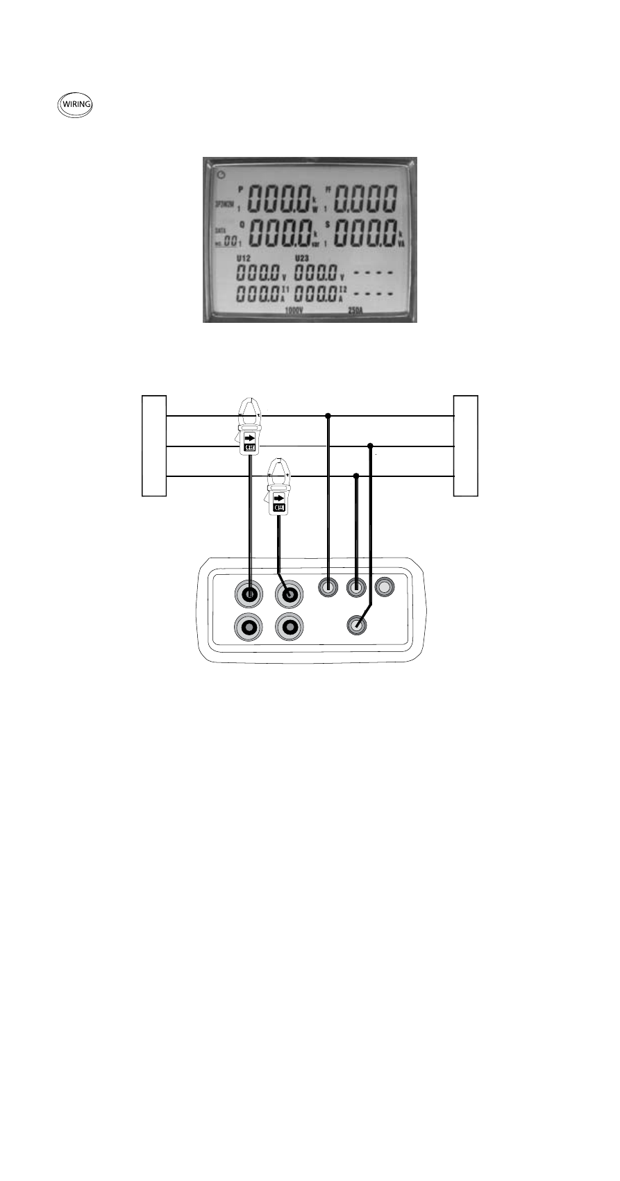
Three-phase Power Measurement, Aron connection –
type of connection 3P3W2M
1) Switch on the instrument.
2)
Select the type of connection 3P3W2M using the “Wiring” function
key (6). After selection, the following display is indicated with the sym-
bol 3P3W2M (5.11):
Display Type of connection 3P3W2M
3) The measurement inputs are connected as illustrated in the following drawing:
I1
I3
I2
I4
U1
U2
U3
N
CURRENT PROBE
CAT III 600V ALL INPUT
INPUT: 0.35mV/A
0.35V MAX
L1
red
black
yellow
L2
L3
Curr
ent Supply
Consume
r
Type of connection 3P3W2M
L1: phase 1
L2: phase 2
L3: phase 3
☞
Shaft direction (X1) (see also page 12)
☞
Current flow direction: The printed arrow on the clamp adapter must point to
the electric power supply.
Connect the test leads to the measurement instrument as follows:
1) Connect black test lead to socket N.
2) Connect red test lead to socket U1.
3) Connect yellow test lead to socket U2.
4) Connect clamp adapter 1 to socket I1.
5) Connect clamp adapter 2 to socket I2.
Now, connect the tests leads using the alligator clips and the clamp adapter to
the electric power supply to be tested.
1) Connect black test lead to Phase L2.
2) Connect red test lead to phase L1.
3) Connect yellow test lead to phase L3.
4) Open the clamp adapter 1 using the clamp opening lever and surround the live
phase 1.
17