Table 5.19 flash rom write cycle, Flash rom read cycle (cont.), Flash rom write cycle – Avago Technologies LSI53C1030 User Manual
Page 140
5-16
Specifications
Version 2.2
Copyright © 2001, 2002, 2003 by LSI Logic Corporation. All rights reserved.
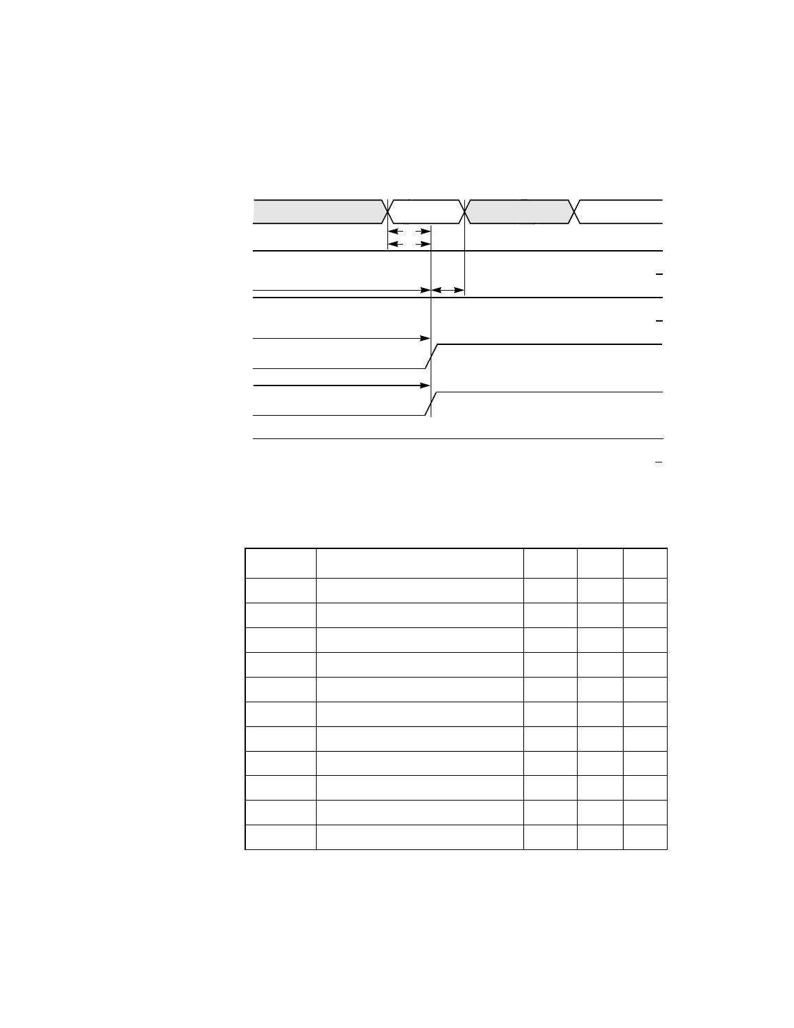
Figure 5.10 Flash ROM Read Cycle (Cont.)
and
provide the timing information for Flash ROM
write accesses.
Data driven by Flash)
MAD Bus
(Addr driven by LSI53C1030;
FLSHALE1/
(Driven by LSI53C1030)
FLSHALE0/
(Driven by LSI53C1030)
FLSHCE/
(Driven by LSI53C1030)
MOE/
(Driven by LSI53C1030)
BWE0/
(Driven by LSI53C1030)
t
4
t
9
t
5
Valid
t
6
t
8
t
7
Read
Data
Table 5.19
Flash ROM Write Cycle
Symbol
Parameter
Min
Max
Unit
t
11
Address setup to FLSHALE/ HIGH
25
–
ns
t
12
Address hold from FLSHALE/ HIGH
25
–
ns
t
13
FLSHALE/ pulse width
25
–
ns
t
20
Data setup to BWE0/ LOW
40
–
ns
t
21
Data hold from BWE0/ HIGH
30
–
ns
t
22
BWE0/ pulse width
20
–
ns
t
23
Address setup to BWE0/ LOW
75
–
ns
t
24
FLSHCE/ LOW to BWE0/ HIGH
60
–
ns
t
25
FLSHCE/ LOW to BWE0/ LOW
25
–
ns
t
26
BWE0/ HIGH to RAMCE/ HIGH
25
–
ns
t
27
FLSHCE/ pulse width
100
–
ns