ProSoft Technology MVI56-BSAPS User Manual
Page 60
MVI56-BSAPS ♦ ControlLogix Platform
Reference
Bristol Babcock Serial Slave Module
Page 60 of 83
ProSoft Technology, Inc.
September 22, 2008
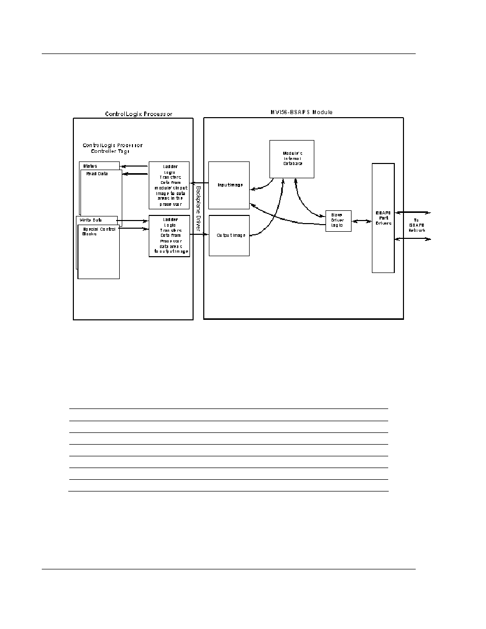
The following illustration shows the data transfer method used to move data
between the ControlLogix processor, the MVI56-BSAPS module, and the BSAP
network.
As shown in the diagram, all data transferred between the module and the
processor over the backplane is through the input and output images. Ladder
logic must be written in the ControlLogix processor to interface the input and
output image data with data defined in the controller tags. All data used by the
module is stored in its internal database.
MVI56-BSAPS Fixed Database Map
Start Address
End Address
Data
0
509
Input Analog Data
510
638
Input Logical Data
640
2740
Input String Data
3000 3509
Output
Analog
Data
3510 3638
Output
Logical
Data
3640
5740
Output String Data
Data contained in this database is paged through the input and output images by
coordination of the ControlLogix ladder logic and the MVI56-BSAPS module's
program. Up to 248 words of data can be transferred from the module to the
processor at a time. Up to 247 words of data per backplane scan can be
transferred from the processor to the module. Each image has a defined
structure depending on the data content and the function of the data transfer
described in the following topics.