5 encoder connection, 1 encoder signal (cn2) names and functions, 2 encoder connection examples – Yaskawa Σ-V Series AC Servo Drives Rotational Motor Analog Voltage Reference User Manual
Page 60: 1) using as an incremental encoder, Analog
3.5 Encoder Connection
3-25
3
Wi
ring and
C
onne
ctio
n
3.5
Encoder Connection
This section describes the encoder signal (CN2) names, functions, and connection examples.
3.5.1
Encoder Signal (CN2) Names and Functions
The following table shows the names and functions of encoder signals (CN2).
∗
It is not necessary to connect these pins to the SERVOPACK.
3.5.2
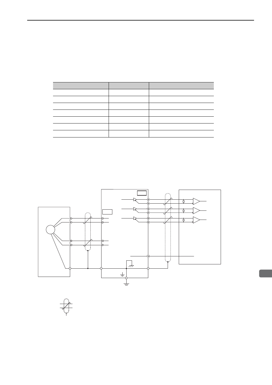
Encoder Connection Examples
The following diagrams show connection examples of the encoder, the SERVOPACK, and the host controller.
(1) Using as an Incremental Encoder
∗
: represents shielded twisted-pair wires.
Signal Name
Pin No.
Function
PG 5 V
1
Encoder power supply +5 V
PG 0 V
2
Encoder power supply 0 V
(BAT (+))*
3
Battery (+)
(BAT (-))*
4
Battery (-)
PS
5
Serial data (+)
/PS
6
Serial data (-)
Shield
Shell
–
21
0 V
SG
13
PA O
/PAO
PBO
/PBO
PCO
/PCO
1
2
5
6
CN2
19
20
22
23
24
ENC
CN1
∗
∗
PS
/PS
PG5V
PG0V
0 V
R
R
R
Incremental encoder
Shielded wire
(Shell)
Connector shell
Connector
shell
Output line-driver SN75ALS174
or the equivalent
Phase A
Phase A
Phase B
Phase B
Phase C
Phase C
SERVOPACK
Host controller
Applicable line receiver: SN75ALS175 or MC3486
manufactured by Texas
Instruments, or the
equivalent
R (terminating resistance): 220 to 470
Ω
Analog