Fifo ip core signals for max 10 devices, Fifo ip core signals for max 10 devices -2 – Altera MAX 10 Embedded Memory User Manual
Page 63
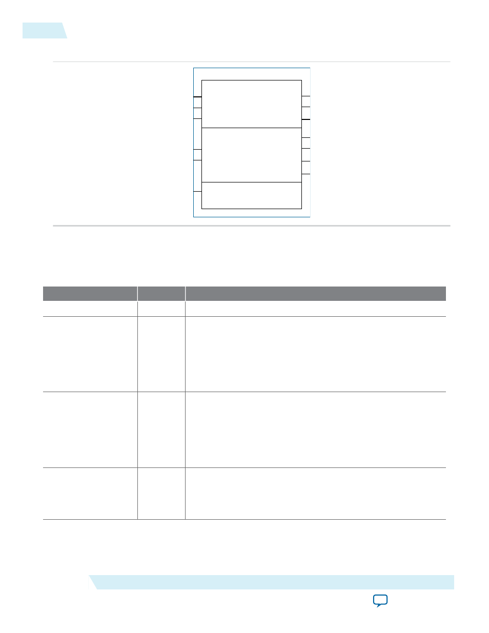
Figure 9-2: FIFO IP Core: DCFIFO Mode Signals
data[]
wrreq
wrclk
wrfull
wrempty
wrusedw[]
rdreq
rdclk
q[]
rdfull
rdempty
rdusedw[]
aclr
FIFO IP Core Signals for MAX 10 Devices
Table 9-1: FIFO IP Core Input Signals
Signal
Required
Description
clock
Yes
Positive-edge-triggered clock.
wrclk
Yes
Positive-edge-triggered clock. Synchronizes the following ports:
•
data
•
wrreq
•
wrfull
•
wrempty
•
wrusedw
rdclk
Yes
Positive-edge-triggered clock. Synchronizes the following ports:
•
q
•
rdreq
•
rdfull
•
rdempty
•
rdusedw
data
Yes
Holds the data to be written in the FIFO IP core when the
wrreq
signal is asserted.
If you manually instantiate the FIFO IP core, ensure that the port
width is equal to the How wide should the FIFO be? parameter.
9-2
FIFO IP Core Signals for MAX 10 Devices
UG-M10MEMORY
2015.05.04
Altera Corporation
FIFO IP Core References