Altera Cyclone II FPGA Starter User Manual
Page 17
Advertising
Altera Corporation
2–3
October 2006
Cyclone II FPGA Starter Development Kit User Guide
Development Board Setup
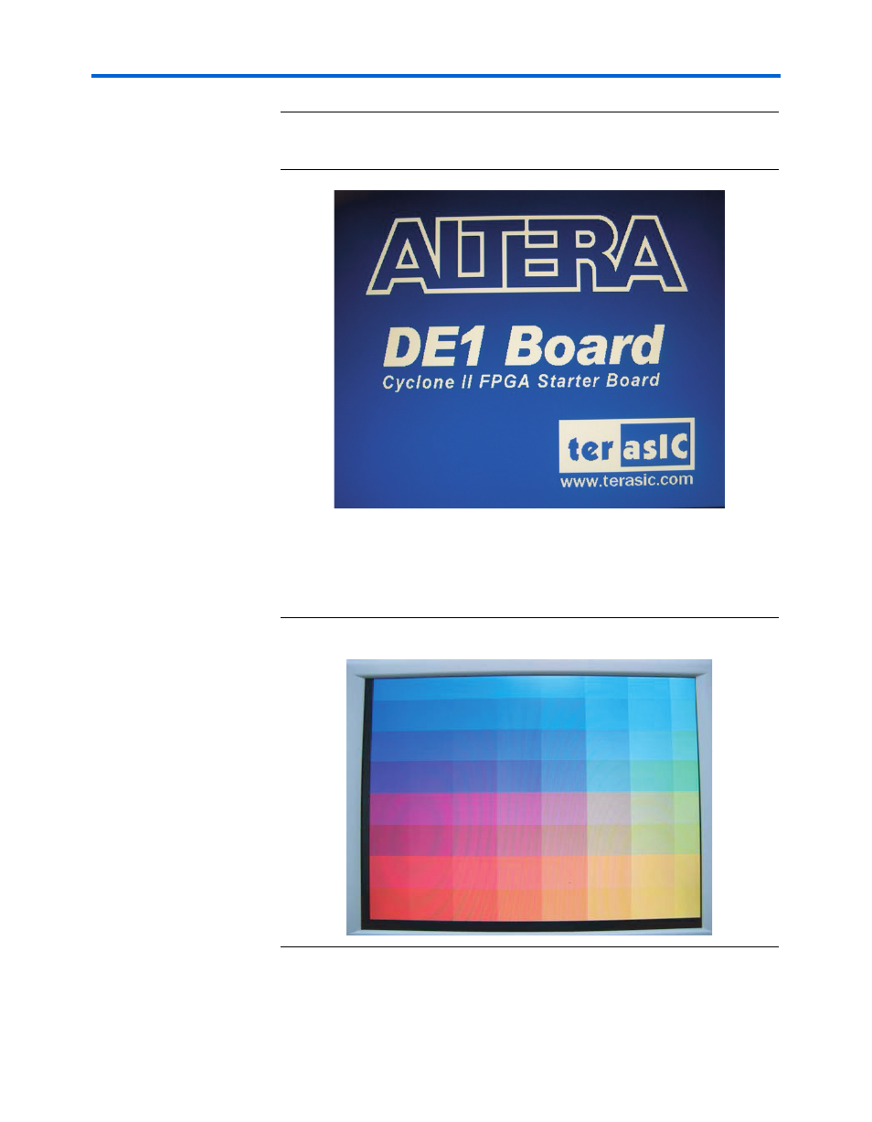
Figure 2–2. Default VGA Output Pattern, SW0 = DOWN
4.
Confirm that the VGA monitor displays the default image
(
) with the SW0 switch set to the UP (away from the edge
of the board) position.
Figure 2–3. Default FGA Output Pattern, SW0 = UP
5.
Set the toggle switch SW9 to the DOWN position and confirm that
the computer produces a 1-kHz tone.
Advertising