3 connection panel at the rear of the unit, 4 triangle instrument panel c 150 – BINDER C 150 User Manual
Page 19
Advertising
C 150 (E2) 12/2012
page 19/90
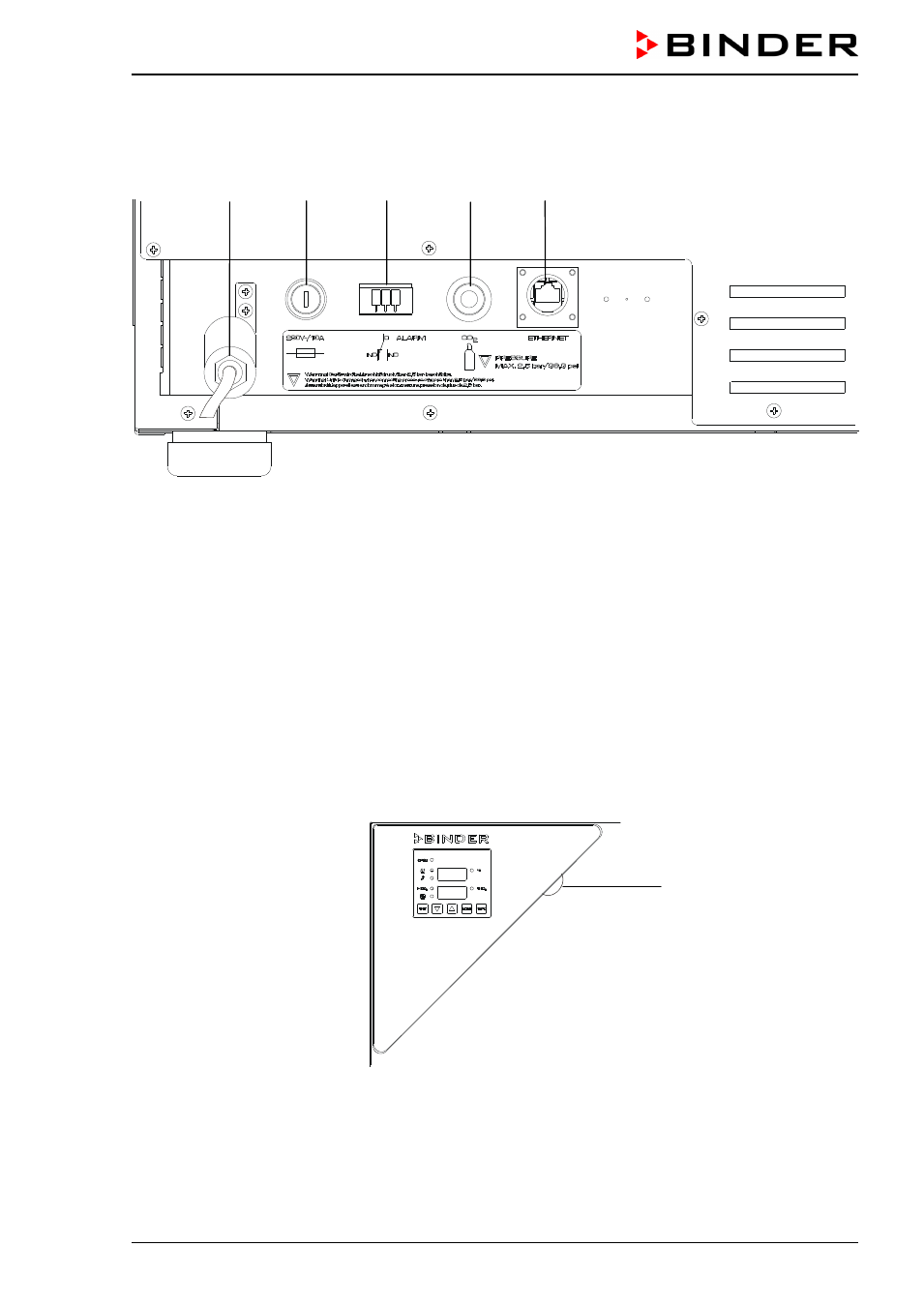
2.3 Connection panel at the rear of the unit
(11)
(12)
(13)
(14)
(15)
Figure 8: Rear connection panel C 150
(11) Power cable
(12) Miniature fuse
(13) Connection socket for zero-voltage relay alarm contact
(14) Quick acting closure socket for CO
2
gas cylinder
(15) Ethernet interface for computer communication (option)
2.4
Triangle instrument panel C 150
Figure 9: Triangle instrument panel with RP1 controller
(2)
Main power switch with protruding plastic shield (protection against turning off unintentionally)
(2)
Advertising