Danger, 3 zero-voltage relay alarm output – BINDER C 150 User Manual
Page 49
C 150 (E2) 12/2012
page 49/90
10.3 Zero-voltage relay alarm output
Collective alarm output via the zero-voltage relay alarm contact
The CO
2
incubator is equipped at the rear with a zero-voltage relay output (13) for the temperature and
CO
2
, which permits the transmission of alarms to an external monitoring system in order to monitor and
record the alarm signals.
The zero-voltag
e relay alarm output switches immediately, as soon as the red LED “ALARM” lights up on
the controller display. The zero-voltage relay alarm output switches for alarm instances listed in chap.
10.1 and in case of power failure.
If the external alarm monitor is connected via the contacts C and NO, alarm monitor-
ing will take place with protection against short-circuiting, i.e., if the connection be-
tween the C 150 and the external alarm monitor is interrupted, an alarm is triggered.
In this case, power failure will also trigger the alarm.
Figure 25: Zero-voltage contacts circuit diagram
C
NO
NC
ALARM
In case there is no alarm, contact C closes with contact NO.
Closing contact C with contact NC switches the zero-voltage relay alarm output.
Maximum loading capacity of the switching contacts: 24V AC/DC
– 2.0 Amp.
DANGER
Electrical hazard.
Danger of death.
Damage to switching contacts and connection socket.
Do NOT exceed the maximum switching load of 24V AC/DC
– 2.0 Amp.
Do NOT connect any devices with a higher loading capacity.
The alarm message on the controller display remains displayed during transmission of an alarm via the
zero-voltage relay outputs.
As soon as the cause of the alarm is identified and resolved, the alarm transmission via the zero-voltage
relay outputs resets automatically together with the alarm message on the controller display.
In case of a power failure, transmission of the alarm via zero-voltage relay outputs remains active for the
duration of the power failure. Afterwards, contact C will close automatically with contact NO.
Connection to an external monitoring system
To ensure short-circuit-proof alarm monitoring that will trigger the alarm when the C 150 is connected to
an external alarm monitor, connect the external alarm monitoring system to the C 150 via the C and NO
contacts.
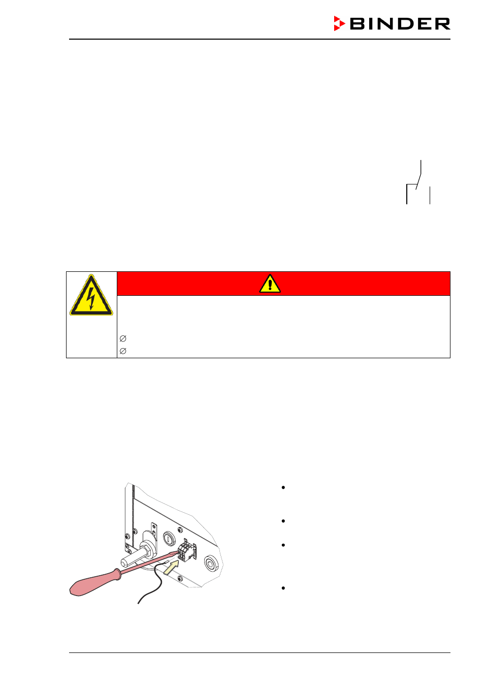
Figure 26: Connection to an external monitoring system
Insert a suitable slotted screwdriver into the
opening in the terminal strip above contact
C.
Press the screwdriver carefully into the
opening. The contact C terminal will open.
Insert the bare end of one of the two cables
on the external alarm monitoring system in-
to the terminal opening and remove the
screwdriver from the terminal strip.
Follow the same procedure with the other
cable on the external alarm monitor, which
you can either connect to contact NC or
NO.