Caution, 9 temperature sensor failure – BINDER C 150 User Manual
Page 53
C 150 (E2) 12/2012
page 53/90
Actions:
Check that you have set the pressure on the pressure reducer at 2.0 bar / 29 psi above the ambient air
pressure, and that all the valves are open for the gas supply.
Where the CO
2
supply is a pressurized gas cylinder, check that the cylinder still contains sufficient
CO
2
. If necessary, replace the gas cylinder. Observe the precautions when handling gases and the
correct outlet pressure (chap. 4.4).
Check whether the primary pressure is high enough at the central CO
2
supply.
Check that the gas tube has no damage, kinks, blockages or soiling.
Check when the gas filter was last replaced. Replace the gas filter every year to avoid it blocking.
A qualified service engineer should replace the gas filter.
If points 1 to 5 do not reveal the source of the fault, it may be that the unit is faulty. Please contact
BINDER Service.
The outlet pressure of the gas cylinder must be 2.0 bar / 29 psi above the ambient pressure.
CAUTION
Excessive outlet pressure > 2.5 bar / 36 psi.
Damage to the unit.
The outlet pressure must NOT exceed the indicated value of 2.5 bar / 36 psi.
Before connecting, check the outlet pressure on the pressure reducer of the cylinder.
Adjust the cylinder outlet pressure to 2.0 bar / 29 psi above the ambient pressure.
The recovery times of the gas concentrations inside the chamber following the door being opened, which
are indicated in the technical data (chap. 19.4), refer to a connection pressure of 2.0 bar / 29 psi. De-
creasing supply pressure down to the alarm point of 0.3 bar / 4.4 psi results in longer recovery times.
Check the pressure displays of your gas supply. If very short recovery times are required or the door is
opened frequently, replace the gas cylinders promptly when the pressure decreases below 2.0 bar / 29
psi.
10.9 Temperature sensor failure
A sensor fault alarm display takes priority over all other operational displays and alarm signals on the
controller.
Immediate alarm
Visual display:
LED
Upper Display, flashing
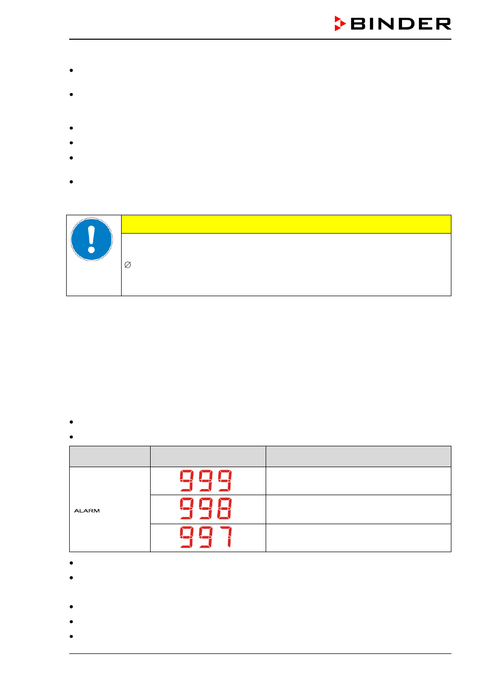
Alarm code
Meaning
Flashes
Failure of temperature sensor for interior heating:
interior heater is turned off
Failure of the safety controller's temperature sen-
sor: all heaters are turned off
Failure of temperature sensor for door heating:
door heater is turned off
Audible alarm: buzzer (intermittent sound)
Switching the zero-voltage relay alarm output
Actions:
Turn off the C 150.
If necessary, clean and disinfect the C 150. Automatic sterilization is not possible with this fault.
Please contact BINDER Service.