Proceed CDP User Manual
Page 19
19
If you choose to use the single-ended outputs of the CDP, connect its right-
channel and left-channel single-ended outputs to the corresponding inputs
on your preamplifier (or power amplifier if you are using the variable out-
put mode of the CDP), using high quality single-ended interconnecting
cable such as Madrigal’s CZ Gel-2.
2
BALANCED ANALOG OUTPUTS
These outputs provide balanced analog audio (via cables equipped with
XLR-type connectors) to a preamplifier, integrated amplifier, or receiver
equipped with balanced inputs. Balanced interconnection between the CDP
and the component that follows it offers the best quality interconnection
and is highly recommended.
If you engage the volume control circuitry in the CDP, these outputs may be
routed directly to a power amplifier that accepts balanced inputs. This
mode of operation is less desirable sonically than using a high quality ac-
tive preamplifier, but may be advantageous under some circumstances.
Note:
When you engage the volume control circuitry in the CDP, the
volume will initially be set to 00 as a safety measure to protect
your loudspeakers. You will need to raise the volume before
you will be able to hear any output from your CDP.
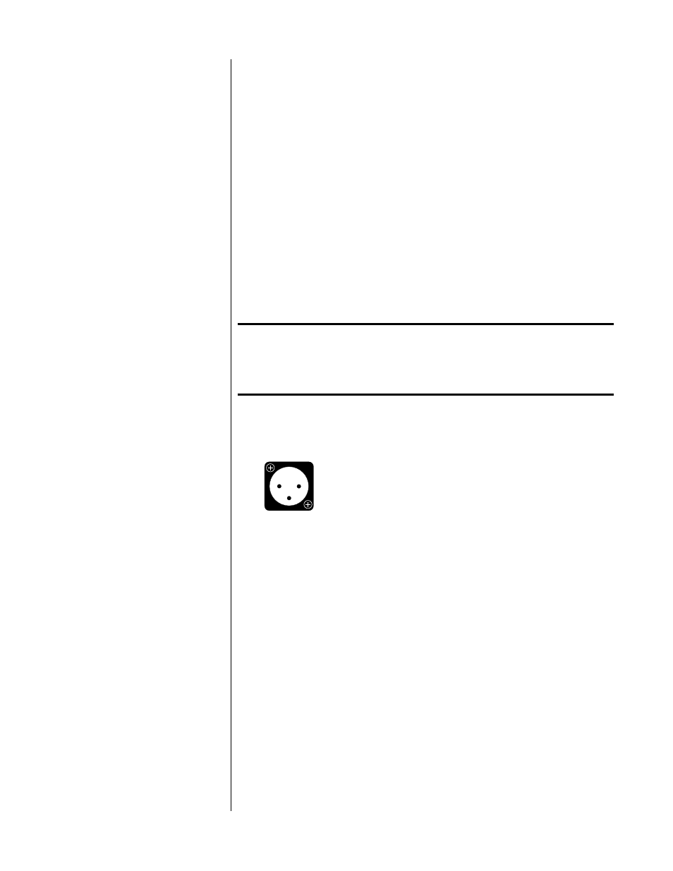
The pin assignments of these XLR-type male outputs conform to the inter-
national AES standard, and are as follows:
1 2
3
Pin 1: Signal ground
Pin 2: Signal + (non-inverting)
Pin 3: Signal – (inverting)
Connector ground lug: chassis ground
Refer to your preamplifier’s operating manual to verify that the pin assign-
ments of its input connectors correspond to the CDP. If not, wire the cable
so that the appropriate output pin connects to the equivalent input pin, or
reverse the leads of both your speaker cables to “reverse the reversal” and
restore correct polarity.
If you choose to use the balanced outputs of the CDP, connect its right-
channel and left-channel balanced outputs to the corresponding inputs on
your preamplifier (or power amplifier if you are using the variable output
mode of the CDP), using high quality balanced interconnecting cable such
as Madrigal’s CZ Gel-1.
3
DIGITAL OUTPUT
This output provides digital audio (via a 75
Ω
cable equipped with RCA-
type connectors) to the digital input of a DAT, CD-R, MD, DCC, or any other
component that accepts an
S
/
PDIF
electrical digital input. It automatically
sends a copy of the currently selected digital source’s datastream to the
connected device for recording or further digital processing. (The digital
output is unaffected by changes in the volume control circuitry of the CDP,
allowing you to adjust volume without affecting your digital recordings.)