Proceed PDSD User Manual
Page 20
20
3
DIGITAL INPUTS 1-6
Please remember to make a note of what sources you connect to which
inputs. You will need to set up the relationships between front panel but-
tons and rear panel connectors later, in the setup menu system. For now,
you can connect any source to any compatible connector—just keep a list
of what-goes-where. (Just such a list is waiting for you later in this manual.
You might want to copy it in order to keep the original clean for future
use.)
1
3
2
5
4
6
digital inputs
PUSH
21
3
Digital Input 1
accepts digital audio in the
EIAJ
optical (sometimes called
“Toslink”) digital interface standard from a digital satellite receiver, compact
disc, laserdisc, DVD or other digital source component. Connect the eiaj
digital output of your source component to the
EIAJ
input of the Digital Sur-
round Decoder using a high quality
EIAJ
optical cable.
Digital Inputs 2-5
accept digital audio conforming to the 75
Ω
S
/
PDIF
digital
interface standard (via cables equipped with RCA-type connectors) from a
digital satellite receiver, compact disc, laserdisc, DVD or other digital source
component. Connect the 75
Ω
S
/
PDIF
output of your source component to
either of these inputs of the Digital Surround Decoder, using a high quality
75
Ω
cable such as Madrigal MDC-2.
Digital Input 6
accepts digital audio in the professional 110
Ω
AES
/
EBU
digital
interface standard (via a cable equipped with
XLR
-type connectors) from a
digital satellite receiver, compact disc, laserdisc, DVD or other digital source
component. Connect the
AES
/
EBU
digital output of your source component
to the
AES
/
EBU
input of the PDSD using a high quality 110
Ω
AES
/
EBU
cable
such as Madrigal MDC-1.
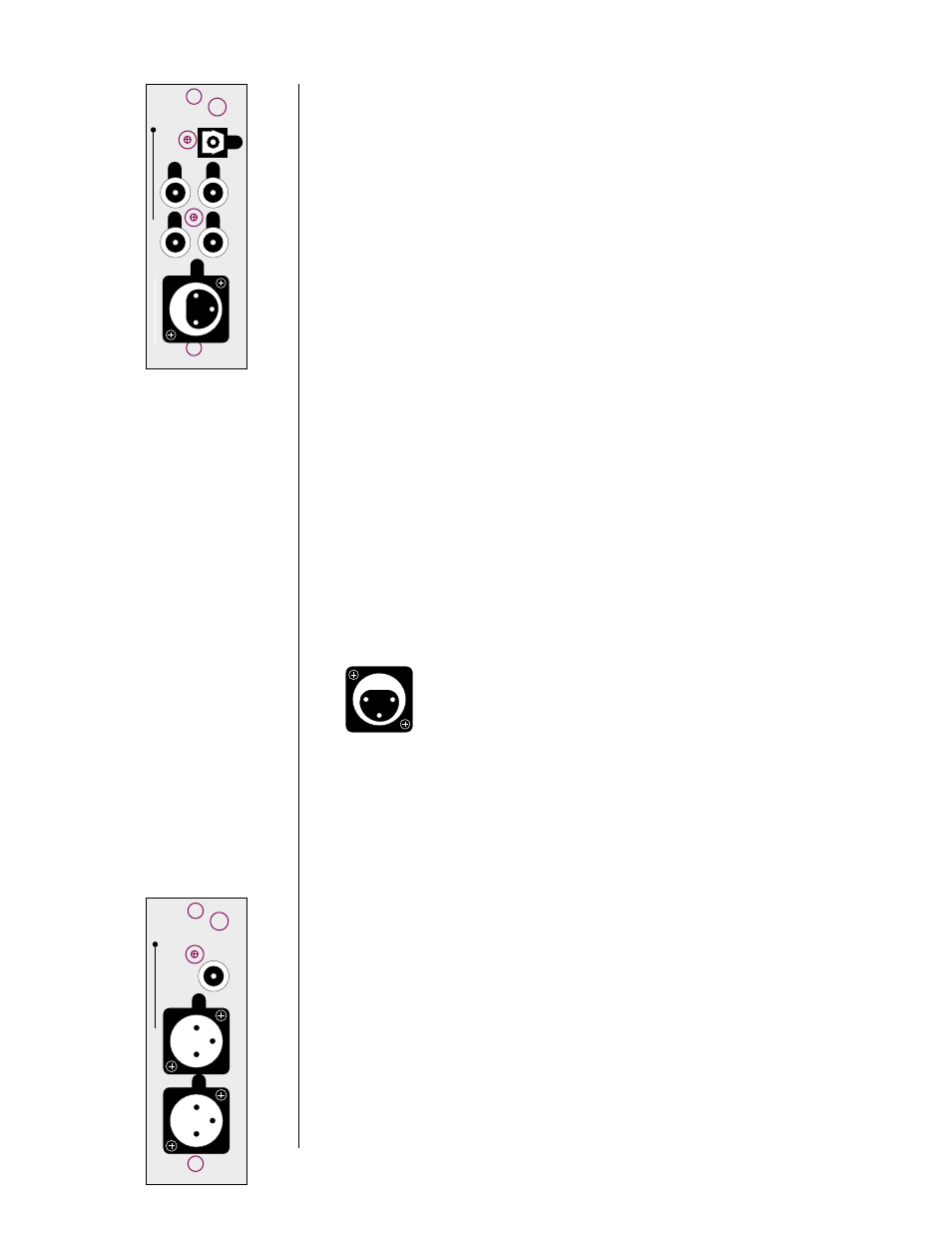
The pin assignments of these
AES
/
EBU
XLR
-type female input connectors are:
PUSH
2 1
3
Pin 1: Shield
Pin 2: Digital + (non-inverting)
Pin 3: Digital – (inverting)
Connector ground lug: chassis ground
These pin assignments are consistent with the standards adopted by the
Audio Engineering Society and the European Broadcast Union. Refer to the
operating manuals of your digital sources to verify that the pin assignments
of their output connectors correspond to the Digital Surround Decoder. If
not, wire the cables so that the appropriate output pin connects to the
equivalent input pin.
4
REMOTE OUTPUT (ANALOG & DIGITAL)
By connecting the balanced (analog) remote outputs in this module to the
bal/aux
input on the PAV, all PCM (normal digital, not Dolby Digital nor
DTS) sources connected directly to the Digital Surround Decoder will be
available for distribution to either the PAV’s
remote zone
or its
record path
.
When you select (on the PAV) such a digital source for either the
remote
zone
or the
record path
, the PDSD will pass that digital signal to this mod-
ule, where it will be converted to analog and forwarded to the PAV, which
will in turn send the signal out its appropriate analog outputs. Note that
sources such as AC-3 and DTS are not available at this two-
channel analog output.
(They are, however, available in their original
digital form at the digital output; see below.)
L
R
12
3
12
3
digital
out
remote output