Proceed PDSD User Manual
Page 21
21
By looping the digital sources back through the PAV in this manner, the PAV
can distribute either analog or digital sources to the remote zone or record
path without your having to think about the details of where the signal origi-
nates.
The remote output module also includes a
S
/
PDIF
(on an
RCA
) digital output,
should you wish to distribute a digital source in its original, unprocessed
digital form. For example, if you had another multichannel system elsewhere
in the home, you could forward a Dolby Digital bitstream to the other sys-
tem from this one—running a single digital cable instead of five or six ana-
log cables for surround sound applications.
Note:
The digital remote output can forward only unprocessed
digital sources to another zone or system. By their nature,
analog sources would be excluded from this method of
distribution unless they were first converted to digital form.
5
PAV PASS-THROUGH
You must connect the six main output channels of the PAV to their corre-
sponding
pav pass-through
inputs on the Digital Surround Decoder. When
listening to an analog source connected to the PAV, any signal processing
will be done in the analog domain (in the PAV), and simply forwarded to
the amplifiers through the PDSD. In this way, you can continue to enjoy the
performance of the PAV with analog sources even while adding the capa-
bilities of the Digital Surround Decoder for digital sources.
One benefit to this approach is that all six channels of the PAV are con-
verted to balanced signals prior to being sent to the power amplifiers (con-
trasted with only two channels of the PAV being balanced when used by
itself). Balanced interconnection between the PDSD and the power amplifi-
ers can result in lower noise and better subjective performance, particularly
when long runs of cable are required.
6
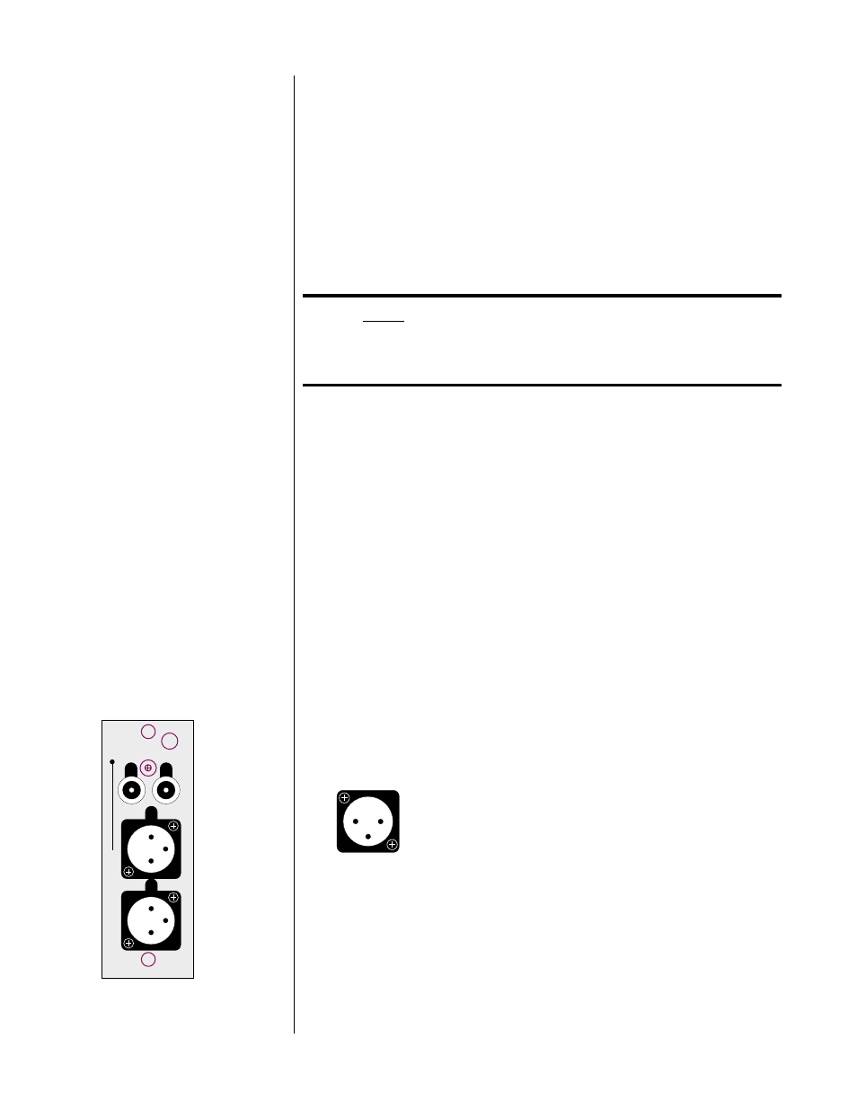
FRONT OUTPUTS
The pin assignments of these XLR-type male outputs conform to the inter-
national AES standard, and are as follows:
R
L
12
3
12
3
L
R
fr
ont output
1 2
3
Pin 1: Signal ground
Pin 2: Signal + (non-inverting)
Pin 3: Signal – (inverting)
Connector ground lug: chassis ground
Refer to your power amplifier’s operating manual to verify that the pin as-
signments of its input connectors correspond to the Digital Surround De-
coder. If not, wire the cable so that the appropriate output pin connects to
the equivalent input pin, or reverse the leads of both your speaker cables to
“reverse the reversal” and restore correct polarity.
High quality single-ended outputs are also provided for compatibility with
power amplifiers lacking balanced inputs.