Alarms for power failure – Signamax Model -065-7700 User Manual
Page 24
Hardened Managed PoE Ethernet Switch
User’s Manual 23
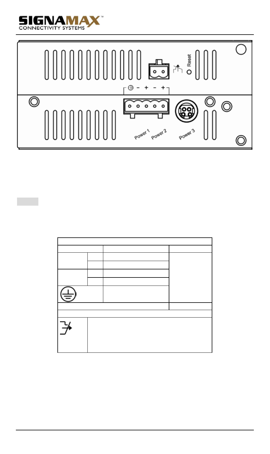
Back View
Alarms for Power Failure
Step 1: There are two pins on the terminal block used for power failure
detection. It provides the normally closed output when the power
source is active. Use this as a dry contact application to send a
signal for power failure detection.
Power Input Assignment
Power3
47-57VDC
DC Jack
Power2
+
47-57VDC
Terminal
Block
-
Power Ground
Power1
+
47-57VDC
-
Power Ground
Earth Ground
Relay Output Rating
1A @ 250VAC
Relay Alarm Assignment
FAULT
*Warning signal disable for following:
3. The relay contact closes if Power1 and
Power2 are both failed but Power3 on.
4. The relay contact closes if Power3 is failed
but Power1 and Power2 are both on.
Special note:
The relay output is normal open position when there is no power to the
switch. Please do not connect any power source to this terminal to
prevent shorting your power supply.