Start-up – Beisler 2211-5 User Manual
Page 42
- C 42 -
Short Seam Automat 2211-5 Working Instructions
Beisler Automated Sewing Equipment
C.3
Start-up
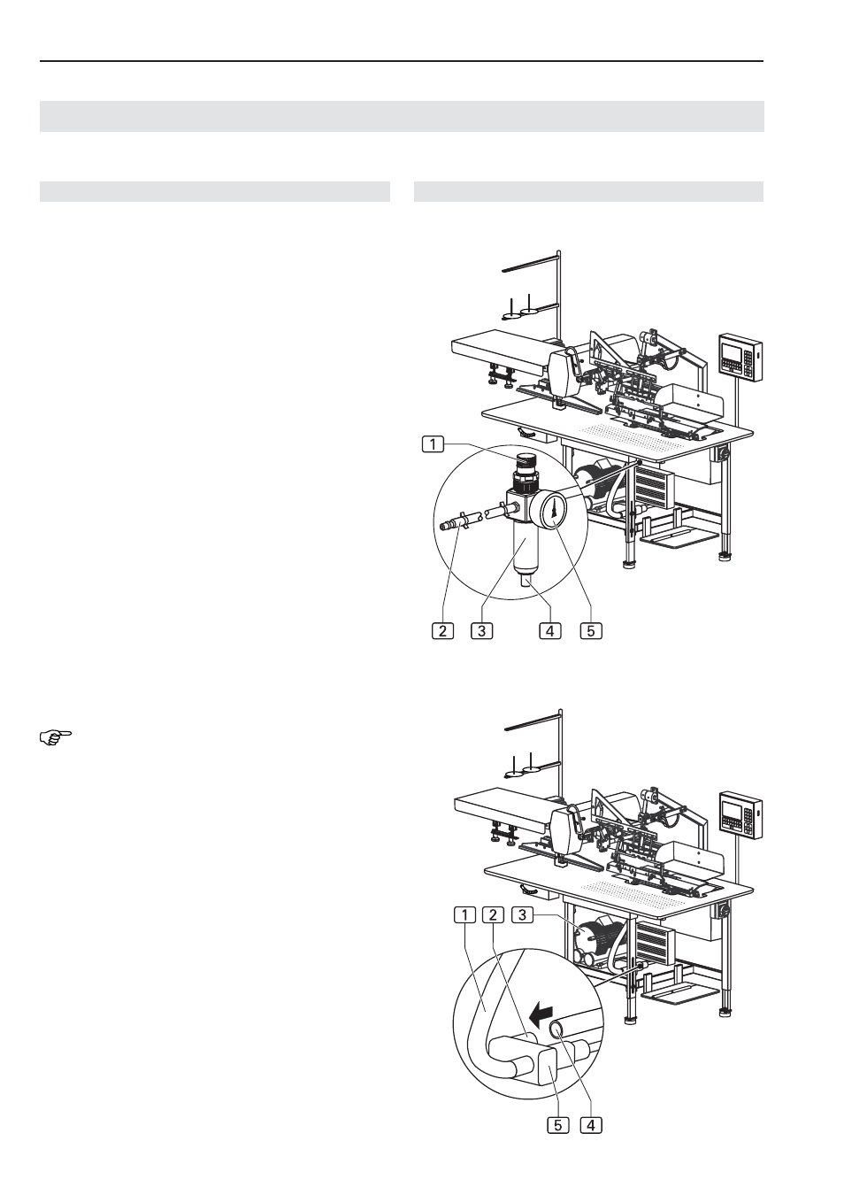
C.3.2 Compressed air / vacuum connections
Fig. 3: The compressed air connection is preinstalled on
the machine. It comprises the following components:
•
Pressure reducer 3 with manometer 5 and water
separator 4,
•
Pressure hose with push-in plug 1.
The pressure reducer is installed at the side mounting wall
of the worktable.
Connecting the machine to the compressed air sup-
ply system:
1. Connect pressure hose plug to on-site terminal unit.
2. Open on-site compressed air supply.
3. Fig. 3: Set pressure reducer to a machine operating
pressure of 6 bar by rotating pressure reducer knob 1
and read value on manometer 5:
• To increase pressure, rotate in clockwise direction.
• To reduce pressure, rotate in counter-clockwise di-
rection.
Connecting the machine to the vacuum supply sy-
stem:
Fig. 4: If the machine is equipped with the optional vacuum
pump 3, no further installation is required. The vacuum
system is ready for operation.
If the machine is delivered without vacuum pump, the on-
site vacuum source must be connected to the machine's
vacuum valve. The vacuum valve 5 is mounted below
the worktable.
NOTE - Required components!
The following components are required on the site:
•
A vacuum hose 3 with an inner diameter of at least
1¼ '' or, as required, an adapter or reducing fitting
to accommodate the on-site vacuum hose on the
sleeve (outer diameter 1¼ '') of the machine's vacu-
um valve.
•
A hose clamp with an inner diameter of at least
1¼ ''.
1. Fig. 4: Connect the on-site vacuum hose to the con-
nection sleeve 4 of the vacuum valve 5.
2. Attach vacuum hose using the hose clamp.
3. Make sure that the vacuum hose 1 to the table pla-
te has been attached correctly and securely.
4. Open on-site vacuum source.
Fig. 3/4
Fig. 3
Fig. 4