3 analog input function block – Flowserve MX FOUNDATION Fieldbus Field Unit User Manual
Page 28
MX/QX FOUNdaTION Fieldbus Field Unit FCd LMENIM2330-01 – 08/11
28
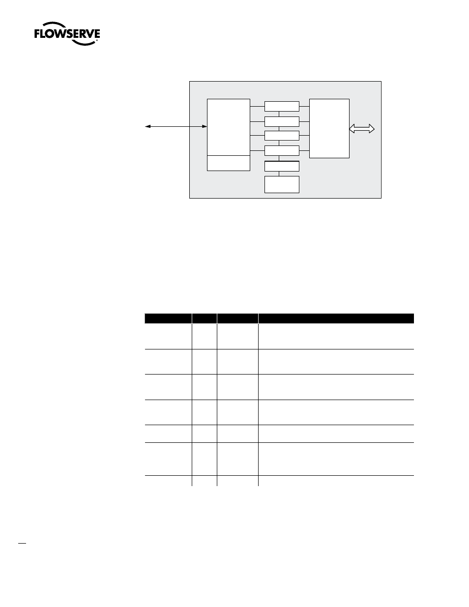
Figure 3.1 – Fieldbus Function Blocks
A Virtual Field Device (VFD) is used to remotely view local device data described in the object
dictionary. The VFD in each device is used for network management and system management, and
contains configuration information such as function block schedules.
The Function Blocks provide the control and I/O behavior of the device. They perform analog to digital
conversion, linearization; and transmit information to and from other function blocks. Function Blocks
are connected together during the configuration to perform the specific control functions of the
process, and communicate with the host device, which supervises the entire control system.
Table 3.1 – Description of the Function Blocks
Function Block
Name
No. of Blocks
Description
Analog Input
AI
1
Processes field device measurements and makes them
available to other function blocks; supports alarming, filtering,
signal status, mode control, and simulation.
Analog Output
AO
1
Assigns an analog setpoint value to a field device through a
transducer block I/O channel; supports mode control, signal
status calculation, and simulation.
Discrete Input
DI
4
Processes a single discrete input from a field device and makes
it available to other function blocks; supports alarming, signal
status propagation, mode control, and simulation.
Discrete Output
DO
2
Processes a discrete setpoint and outputs it to a specified I/O
channel to produce an output signal; supports mode control,
output tracking, and simulation.
Transducer Block
1
A custom block to monitor and control the actuator; connects
function blocks to local input/output functions.
PID Block
PID
1
Combines all necessary logic algorithms to perform process
control; supports mode control, signal scaling and limiting,
feed forward control, override tracking, alarm limit detection
and signal status propagation.
Resource Block
1
A standard block to provide general management of the device.
Standard Fieldbus parameters used in these blocks are listed in Appendix C.
3.3 Analog Input Function Block
The Analog Input (AI) function block (Figure 3.2) is a standard block over all fieldbus systems. The AI
block processes field measurements and makes them available to other function blocks. The output
value from the AI block is in engineering units and contains a status indicating the quality of the
Communication
Resource Block
AI Blocks
DO Blocks
AO Blocks
DI Blocks
Actuator
Fieldbus
Network
Actuator
I/O
Transducer
Block
Function
Blocks
PID Blocks