System components and installation, 1 introduction, 2 hardware – Flowserve MX FOUNDATION Fieldbus Field Unit User Manual
Page 9
9
MX/QX FOUNdaTION Fieldbus Field Unit FCd LMENIM2330-01 – 08/11
flowserve.com
2
System Components
and Installation
2.1 Introduction
This section is an overview of the components used in the FOUNDATION fieldbus system and their
installation. The MX/QX FF unit is installed in the MX or QX actuator as shown in Figures 2.1 and 2.2.
The network cable connects to the fieldbus unit at the actuator terminal block. The network cable
connects all the fieldbus actuators to the distributed control system, which usually acts as the host
and LAS.
2.2 Hardware
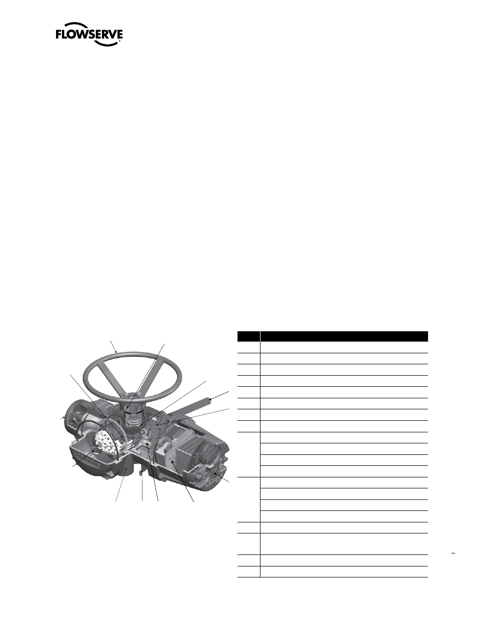
Figure 2.1 – MX-05 Actuator
1
3
4
14
9
10
13
8
7
6
5
2
11
Table 2.1 – MX Actuator Components
No.
Description
1
Top-mounted handwheel
2
Drive sleeve
3
Worm shaft
4
Motor
5
Declutch lever
6
Encoder
7
Control panel (CP)
8
Control module
9
Optional bases
Thrust base type
• A1 = Standard thrust base
• A1E = Extended-reach thrust base
10
Baseplate-type B4 with stem nut options type:
• B4 = stem nut with variable bore and key
• B4E = extended-reach stem nut with variable bore and key
• BL = splined stem nut (SAE or Involute)
11
Handwheel adapter/handwheel worm gear
12
Side-mounted handwheel (not shown, but available for the
MX-10, -20,-85, -140, and -150)
13
Encoder drive cartridge
14
Terminal block