MacroSystem Columbus User Manual
Page 13
12
13
you can select the “Line type” (continuous or
various types of dashed line), the “Line width”
and the “Line color”.
If you have configured the setting so that a line
will not be drawn out, you will see a thin grayish
white line instead which displays the course that
the route takes. This will of course be left out
when the calculations are carried out later on.
Even if the time control in the top right of this
menu (Chapter 3.7) is not set to maximum, the
dashed-line setting will still be selected for the
remaining time of the scene.
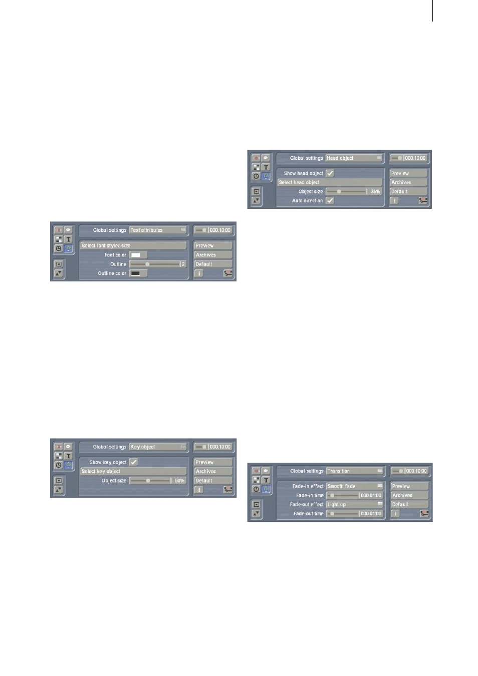
3.6.2 Text attributes
You can use any font installed on the Casablanca
when working with Columbus (except for the
DEMO fonts). Under the “Select font style/size”
setting, you can configure the font type and
size. You can use “Font color” to set the color in
which the font will be drawn. “Outline” can be
used to draw an outline around the letters (the
outline strength can be adjusted) and the “Out-
line color” allows you to select its color.
3.6.3 Key object
The key object is an object that is displayed at
the key points. It is displayed in exactly the same
way at all the key points that have their key
objects setting set to “Global” (default setting).
Firstly, the key object display can be activated or
deactivated using the “Show key object” set-
ting. If it is activated, you can select the object
using “Select key object”. A selection window
(similar to the familiar pattern selection window
- see Chapter 3.11) opens allowing you to make
your selection.
Furthermore, you can adjust the “Object size”.
The „Key position” and “Key view” selec-
tion items in the “Global settings” allow you
to change the position and the rotation of the
objects.
3.6.4 Head object
The head object is directly linked to the line
growth and moves simultaneously with the head
of the line (i.e. the leading end). Basically the
same selection and settings options are avail-
able as for the key objects. An additional setting
for “Head object” allows you to make the direc-
tion of the head object change automatically. If
“Auto direction“ is activated (default setting),
the head object is continuously rotated automat-
ically so that it points in the direction in which
the line is growing. This ensures, for instance,
that an aircraft symbol will always appear to fly
forwards and not sideways or backwards. This
option should be deactivated for 2D objects.
You can change the position and rotation of
head objects using the “Head position” and
“Head view” selection items.
3.6.5 Transition
This is where you can define a transition that
applies to all key points whose transition setting
has been set to “Global”.
The settings correspond to those in the “Transi-
tions” menu.