MBM Corporation 1500S User Manual
Page 13
Advertising
13
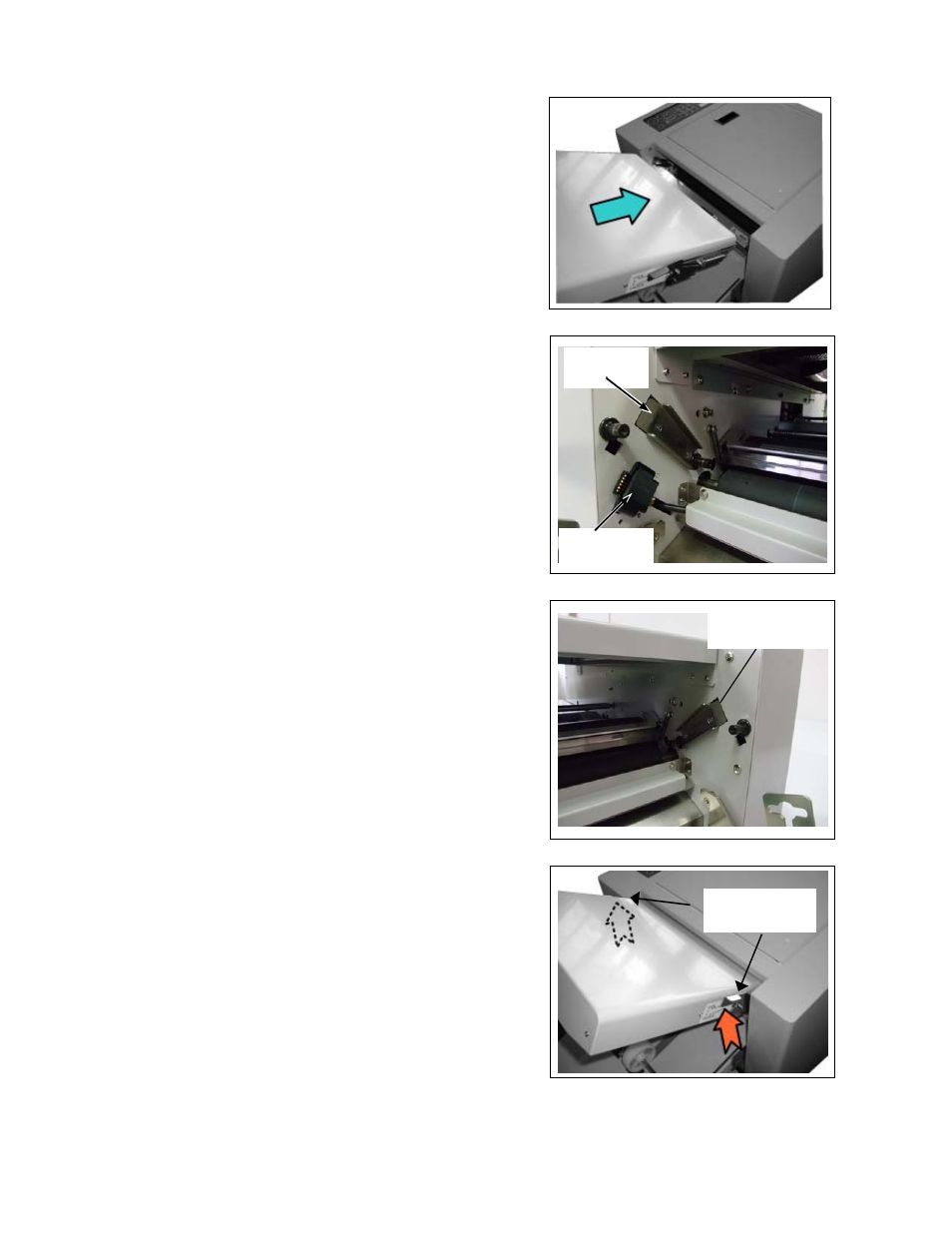
(B) Setting of Table 1
Slide Table 1 bracket (RH&LH) slowly to diagonal direction
along the guide of the main machine body.
Table 1 guide on the operator side
The Table 1 connector is set on the operator’s side. Give
caution not to damage the connector when installing the
Table 1.
Guide
Connector
Table 1 guide on the opposite side of the operator.
Install Table 1 to the main machine body securely and fix it
using the lock levers located on both sides. (Move top of the
lock lever to the arrow direction as shown in the right figure.)
Table 1 Guide
Lock Lever
Advertising