Chapter 7: communications, 1 rs-232 serial – Microcom LDSII User Manual
Page 109
LDSII Programming Guide - 880015-0123
93
Chapter 7: Communications
7.1
RS-232 Serial
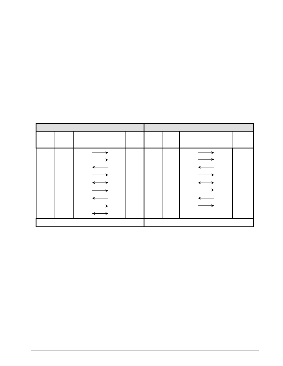
The printer provides a 9 pin female D-Sub connector, on the rear panel, for RS-232 serial
communication. The printer is configured as DCE (Data Circuit-terminating Equipment) so a
NULL modem cable is not necessary. A serial data cable is required to use serial
communications, refer to the table below for correct cable configurations.
The factory settings, unless otherwise requested, are set at 9600 baud, 8 data bits, 1 stop
bit, and no parity with both hardware and software handshaking. The baud rate is user
selectable from 1200 to 230,400 and uses software XON/XOFF flow control and/or
hardware CTS handshaking.
9 to 9 Pin Cable
9 to 25 Pin Cable
State
426
DE-9
Pin #
Signals / Direction
PC
DE-9
Pin #
State
426
DE-9
Pin #
Signals / Directions
PC
DB-25
Pin #
XX
1
DCD
DCD
1
HI
1
DCD
DCD
8
XX
2
TXD
RXD
2
XX
2
TXD
RXD
3
XX
3
RXD
TXD
3
XX
3
RXD
TXD
2
HI
4
DTR
DSR
4
HI
4
DTR
DSR
20
LO
5
GND
GND
5
LO
5
GND
GND
7
HI
6
DSR
DTR
6
HI
6
DSR
DTR
6
DC
7
RTS
CTS
7
DC
7
RTS
CTS
4
XX
8
CTS
RTS
8
XX
8
CTS
RTS
5
HI
9
+5V
+5V
9
HI
9
+5V
-
DC = DO NOT CARE
XX = INDETERMINATE
Table 20
RS-232 Cable Configurations
If XON/XOFF handshaking is used, only signals RXD, TXD, and GND are required for
proper operation. If the hardware handshaking is used the CTS and RTS signals are
required. The other signals are offered in the event that the host computer requires them.
7.1.1
RS-232 Printer Cables
The printer uses standard cables that may be purchased through Microcom Corporation or a
local computer supply company. A NULL-modem cable is not required because the printer
is configured as DCE.