Microcom LDSII User Manual
Page 66
Advertising
Printer Commands
Chapter 2
50
LDSII Programming Guide - 880015-0123
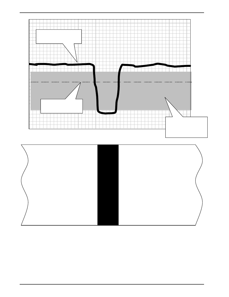
Figure 10
^D900 Blackline Threshold Example
2.7.1.2
Die-Cut/Blowhole Threshold Calculation Example
Follow the process outlined below for an example to determine the die-cut/blowhole or
transmissive sensor threshold calculation. The values reported will vary depending on the
different types of media used.
1. Verify that the sensors are clean and are unobstructed.
300
250
200
150
100
50
0
Threshold
– 128
(Factory Setting)
On-Screen Sensor
value
Grey indicates
acceptable
Threshold values
Advertising
This manual is related to the following products: