Operation, 2 meter and indicator lights while operating – MMD Equipment 25S-3A3 User Manual
Page 39
5. Operation
5-9
5.2.2 Meter and Indicator Lights while Operating
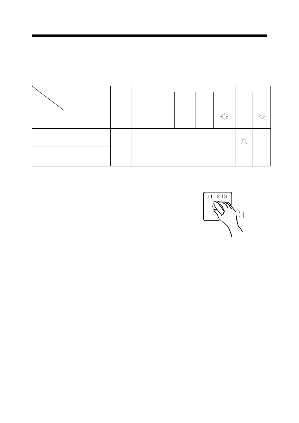
During normal operation, each indication of instruments is shown in the table below. Refer
to the table for daily checks.
Note; The values marked ※ vary with location of the voltage selector switch.
Warning Lamp
Display Lamp
Voltmeter
(V)
Frequenc
y meter
(Hz)
Ammeter
(A)
Over
crank
Over
speed
Oil
pressure
Engine
temper
ture.
Charge Run Glow
Before
Starting up
(preheating)
0
0
0
●
Off
●
Off
●
Off
●
Off
On
●
Off
On
During
Operation
(Full load)
240
480
60
During
Operation
(Unload)
240
480
62.5
Less
than
rated
current
●
Off
On
●
Off
Be sure to frequently check meters and indicators for
proper operation, or any machine water, oil, fuel leaks,
etc.
The above table gives standard values. They may vary
slightly depending on operating conditions and other
factors.
In single-phase load operation, check the current of
L1, L2, and L3 phase with the ammeter, by turning
the ammeter change-over switch.
Each current should be balanced if unbalanced.
Change load connections so the current of L1, L2, and
L3 is equally balanced. Make sure that the current of
each phase does not exceed the rated one.
When the voltage selector switch is in the
single-phase 240/120V position, place the ammeter
change-over switch to the L1 or L3 position to read
the output.
A040164
Ammeter change-over switch
※
※