Installation – Montigo H36PVN User Manual
Page 15
H36PVN Power Vent Indoor Gas Fireplace
Page 15
XG0649 - 031511
Installation
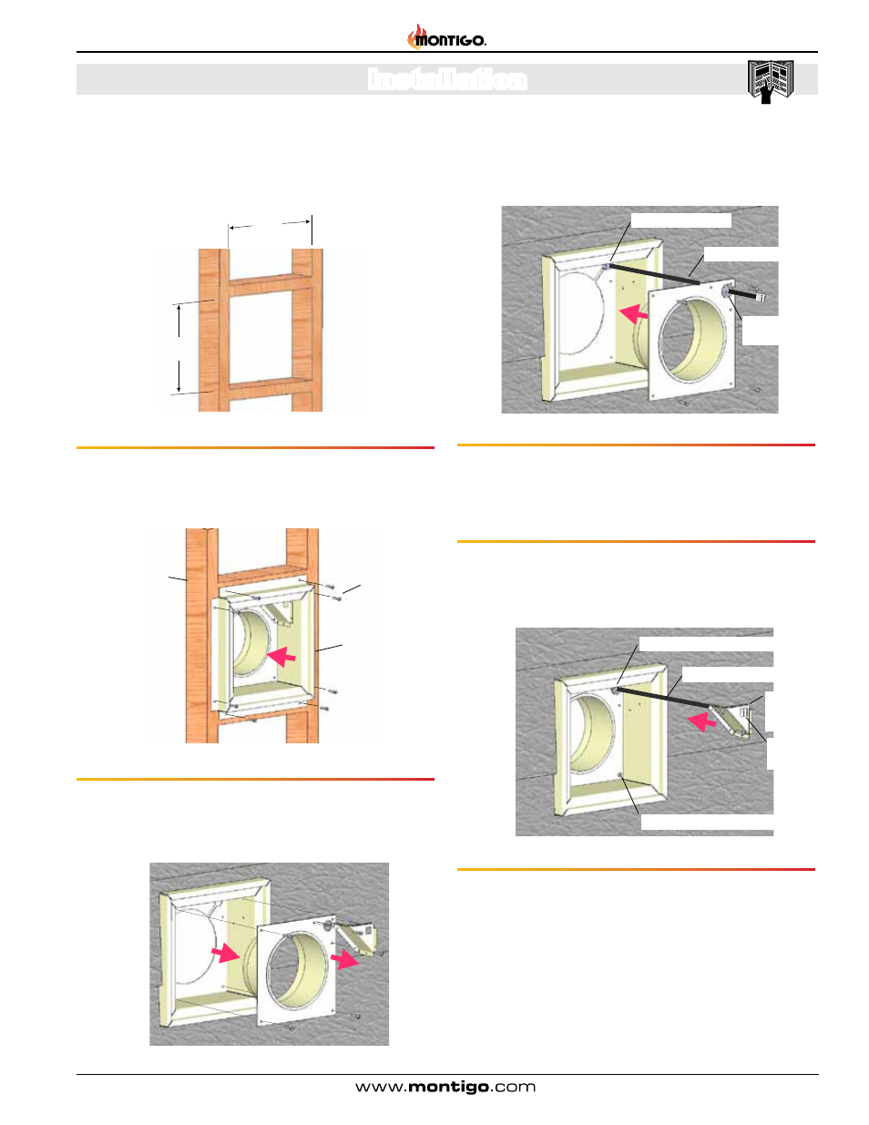
Figure 7. Framing the Opening for Power Vent
14 1/2”
14 1/2”
(Opening)
(Opening)
Step 2.
Insert the Power Vent Rough-in Box as shown in Figure 7a .
Fasten the Box securely in place with Screws or nails . Apply exterior
sheathing and finishing if required .
Step 3.
Next, remove the bottom collar and conduit mounting frame as
shown Figure 7b . (Place removed hardware in a handy location for
re-assembly) .
Figure 7a. Orientation, Placing the Power Vent Inner Box
Framing
Rough-in Frame
Fasteners
Figure 7b. Installation of Rough-in Kit
Installing the external wall mounted power vent module
Step 1. Construct a frame for the termination opening to meet the
following requirements:
■ Opening Size must be: 14 1/2" x 14 1/2" .
Figure 7c. Installation of Power Vent Conduit
Power Vent Conduit
Strain Relief
Nut
Step 4.
Insert the conduit from the Power Vent Module into the rough-in
frame through the two top right entry holes . Remove the nut from the
supplied strain relief and place as shown, Figure 7c .
Strain Relief
Figure 7d. (Installing Conduit connector & conduit mounting frame)
Power Vent Conduit
Strain Relief & tightened nut
Power Vent
Connector
Conduit
mounting
frame
Step 5.
Securely fasten bottom Collar pan into the Rough-in frame using
the existing hardware, (4-pcs) . Tighten Strain Relief nut onto Strain
relief .
Step 6.
Pull Power Vent Connector, (from behind) half-way through
supplied hole in conduit mounting frame, and snap into place, (notches
in two plastic wing clips . Orientation not critical) .
Tightened hardware, 4-pcs.
Step 7.
Fasten Conduit mounting frame into place using existing hardware,
(6-pcs) . (Coil conduit in behind cover .)