Installation, Installation of the ldvpv58 power vent module, Framing dimensions – Montigo H36PVN User Manual
Page 19
H36PVN Power Vent Indoor Gas Fireplace
Page 19
XG0649 - 031511
Installation
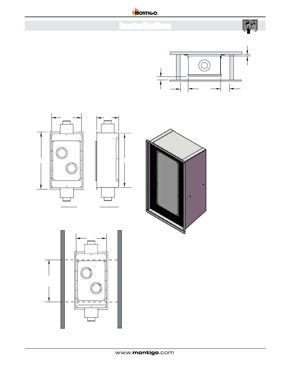
Installation of the LDVPV58 power vent module:
1 . The linear power vent can be installed to existing stud
construction or directly to cement wall or roof . The
LDVPV58
must maintain the clearance to combustibles as shown in Figure
9a . The required service access panel must be framed at 28"
X 18" . To enclose the service access panel, (at less than 2") a
minimum 30% free air must be supplied at all times .
2 . Plug the power cord into the available slot in the linear power
vent .
3 . Secure all venting joints with at least three screws and ensure
that the joints are properly sealed by applying high temperature
silicone .
Figure 9 . LDVPV58 Power Vent overall dimensions.
Top View Side View
Figure 9b . LDVPV58 Power Vent framing dimensions.
Framing Dimensions
Figure 9a . LDVPV58 Power Vent framing dimensions.
The VLWB-8 termination is
designed to be installed flush
with the exterior of the building .
This recessed design uses 5"/8"
vent and allows the installation to
be clean and flush so it does not
interfere or have an impact with
your architectural design .
NOTE:
The
H36PVN requires a specific volume of atmospheric interchange
to operate properly and efficiently
The fireplace requires a MIN 80in/sq . air movement to function .
The grille must also be able to shed water, not allowing any
moisture to enter the unit .
Recessed Termination Installation (VLWB-8) Refer to Appendix A -
Termination locations
Figure 10. Linear Power Vent recessed Termination.
13 5/16"
21 3/8"
18 1/8"
5
8
20 3/16"
12 9/64"
7 13/16"
2
1
ISOMETRIC VIEW
(NTS)
NTS
SIZE DWG. NO.
A
REV.
SHEET 1 OF 1
WEIGHT:
VLWB-8
FINISH
MATERIAL
DIMENSIONS ARE IN INCHES
TOLERANCES:
FRACTIONAL
1/32"
TWO PLACE DECIMAL
.015"
THREE PLACE DECIMAL
.005"
ALL BENDS ARE ASSUMED
TO BE 90 UNLESS NOTED
OTHERWISE.
CHECKED BY
DRAWN BY
LF
DATE
NAME
7/29/2010
304 S.S.T.
TERMINATION, VERTICAL MOUNT, 5/8", 12" X 20" BOX
THE INFORMATION CONTAINED IN THIS DRAWING IS THE SOLE PROPERTY OF CANADIAN HEATING PRODUCTS. ANY REPRODUCTION IN PART OR AS A WHOLE WITHOUT THE WRITTEN PERMISSION OF CANADIAN HEATING PRODUCTS IS PROHIBITED.
PROPRIETARY AND CONFIDENTIAL
Z:\CADD\2007 CADD\Standard\TERMINATIONS\VERTICAL TERMS\VLWB-8\VLWB-8
Thursday, July 29, 2010 10:14:21 AM
SCALE
Access Cover
16 1/2
33 8
11
34 7/8
Access Cover
181/2
28
clearance
for Cover access
5 MIN
5 MIN
Must be left clear on both
ends of Power Vent for
adequate ventilation.
2 MIN
5
MIN
5
MIN
1/2
MIN
Louvres
Vent