Maintenance, Removing the stand-off panels, Removing the access panel – Montigo H36PVN User Manual
Page 31
H36PVN Power Vent Indoor Gas Fireplace
Page 31
XG0649 - 031511
Maintenance
Removing the Stand-off Panels:
The
H36PVN is supplied two (2) two Stand-off Panels (RH & LH) that
hold the firebox refractory Lining in place . These panels are fastened
directly to the interior sides of the firebox with sheet metal screws . To
remove the panels follow the steps described below:
Step 1. Remove the two (2) RH-TOP machine screw that hold
the Side panels in place, then the bottom two (2) machine screws,
Figure 24 . (Philips head screwdriver required).
1
2
3
4
Top
Figure 24. (Removing interior stand-off panel hardware).
Figure 24. (Inset).
Step 2. Tilt the panel out from the top, and remove the panel from
the firebox . Pull out of the firebox straight, toward you without hitting
the Grate or panel Retaining brackets, Figure 24a .
Note: Place the panel somewhere safe where it will not get
damaged.
Step 3. Follow step1 & 2 to remove the LH-Side panel, Figure 24
& 24a . (Philips head screwdriver required).
Figure 24a. (Removing interior stand-off panels).
Side panel
retaining bracket,
4-places
Grate
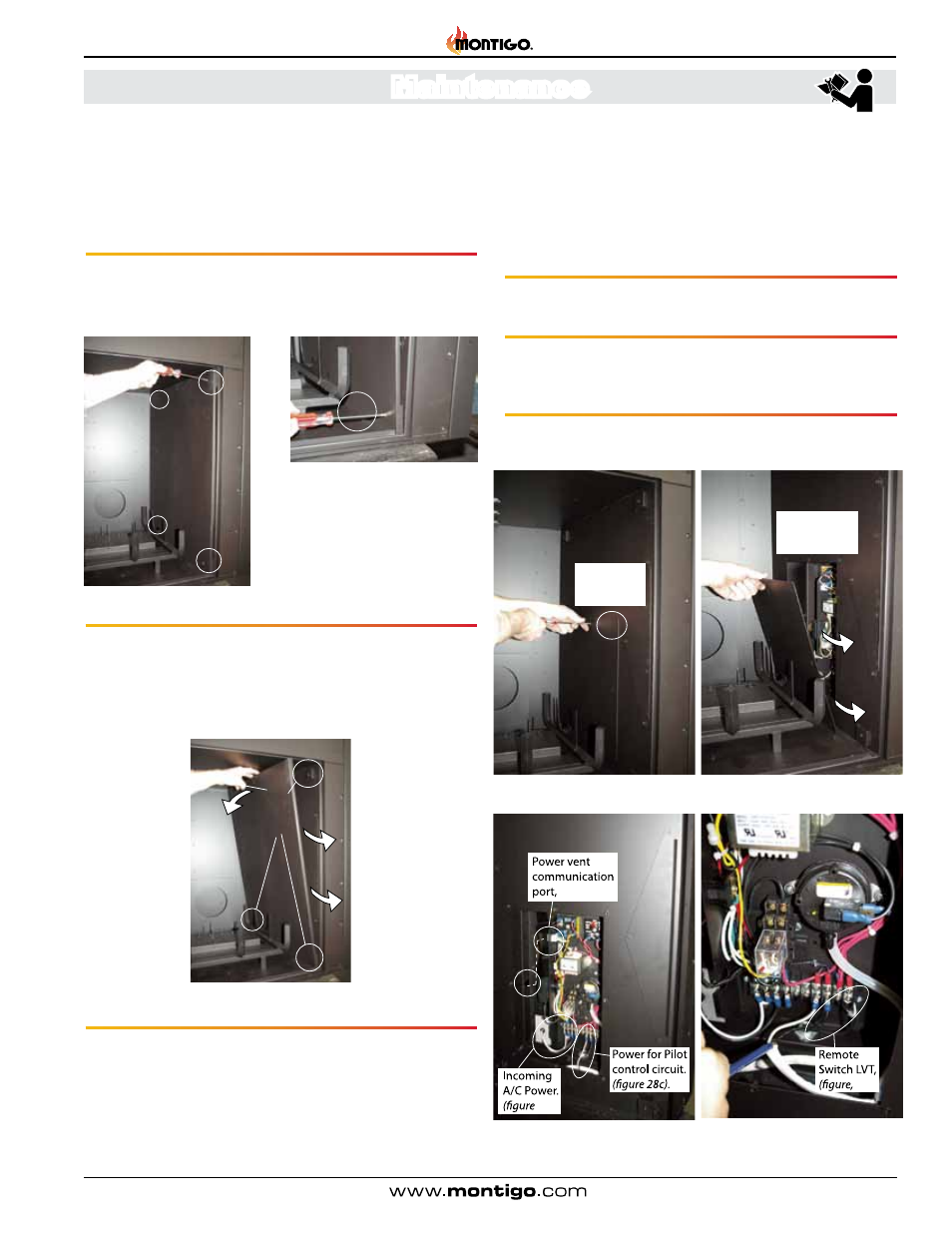
Removing the Access Panel:
The
H36PVN is supplied one (1) one interior access Panel (RH-side)
that contains the electronics and power control circuits . This panel is
fastened directly to the interior of the firebox with sheet metal screws .
To remove the panel follow the steps below:
Step 1. Remove the RH Refractory Panel as described in Figure 22 .
Step 2. Remove the RH Refractory Stand-off Panel as described
in Figure 24 & 24a .
Step 3. Having these two steps completed, remove the eight (8)
machine screw that hold the Side panels in place, Figure 26 . (Philips
head screwdriver required).
Step 4. Slightly tilt panel, and pull out between the grate and firebox
wall, Figure 26a .
Figure 26. (Removing the panel hardware). Figure 26a. (Removing the panel from
the firebox).
Figure 26b. (A/C Connections, Gas
module and fireplace chassis). See figure
13, Schematic).
Figure 26c. (Remote LVT Switch
connection). See figure 13, Schematic).
,
Access Panel
7-pcs
hardware
Grate
Power Vent
Control Access
Panel
Blk Wht
12f)
.
12d).
12).