Installation – Montigo H36PVN User Manual
Page 21
H36PVN Power Vent Indoor Gas Fireplace
Page 21
XG0649 - 031511
Installation
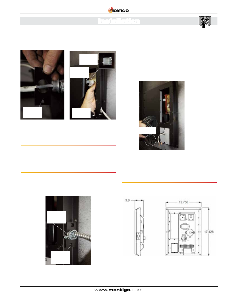
Figure 12c. Remove Exterior Access
Cover.
Figure 12d. Locate Power vent
connections.
Step 7. Tighten Power Vent Strain relief adjustmsent screw, Figure 12e.
Step 6. Re-Install the communication harness Port cover, Figure
12e . (Philips head screwdriver required).
Step 5. Route the Power Vent Comunication conduit into the cover
as shown, and connect to the communication Port, Figure 12d .
Note orientation of conduit plug into the Port, (flat side / notches).
Figure 12e. Installing Conduit Port Cover Plate.
Note
orientation of
connector
Power vent
communication
harness port
Power vent
communication
harness.
Power vent
communication
port cover.
Power vent
communication
port cover strain
relief.
Power vent
communication
port cover
fasteners.
Installing The Remote Switch
The
H36PVN's Remote LVT (Low Voltage) Switch conduit is located
on the RH Side of the fireplace .
Note: The switch location must not exceed 30' from the fireplace .
Remote
Switch LVT
Figure 12g. Electrical Enclosure Dimensions
Figure 12f. Installing the Remote LVT Switch.