Installation, Installing the logs – Montigo H36PVN User Manual
Page 26
H36PVN Power Vent Indoor Gas Fireplace
Page 26
XG0649 - 031511
Installation
Section 8: Installing the Log Set
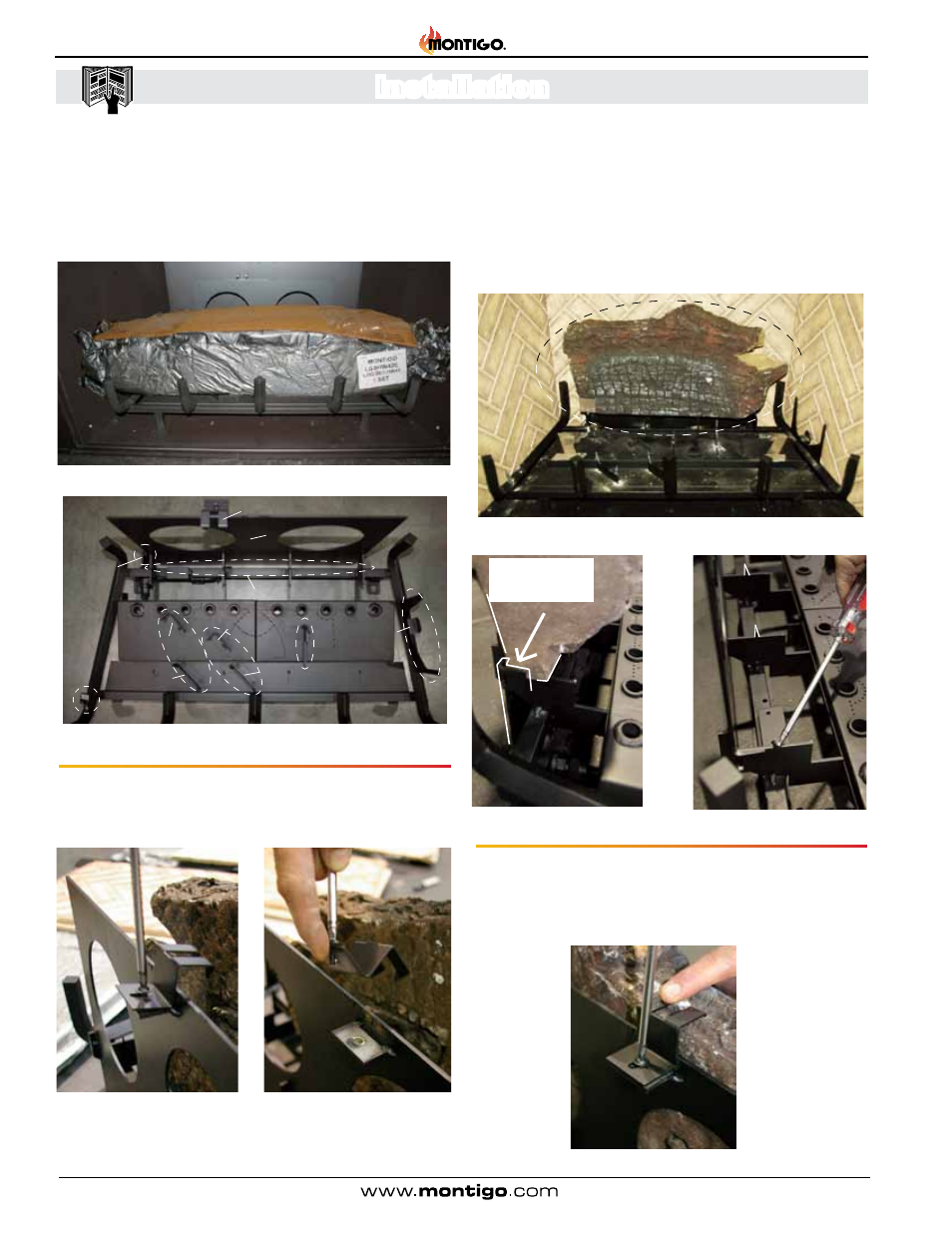
Installing the Logs:
The
H36PVN is supplied with six (6) piece ceramic fibre logs . Install
as described below:
Step 1. Unpack the logs and handle them very carefully . Set them
aside in a safe location until required .
Figure 18d. Location of Log 'A'.
Figure 18. Packaged LogSet as supplied from Montigo.
Step 2. Locate the Log Back Pan Retaining clip, Figure, 18a above
and remove, Figures, 18b & 18c . Place in a safe location
(
Philips head screwdriver required).
Step 3. Position Back Log 'A' from the previously unpacked package,
(Figure 18) . Place the Log upright, (as shown Figure 18d) and
move the Log flush against the sheet metal Back Pan . Without
pressing the Log down, move it as far to the left as possible,
bumping the bottom Left corner against the alignment tab,
(Figure 18a & 18d) . Lastly, Press the Log FIRMLY downward,
onto the sharp spikes, shown in Figure 18a & 18e.
Step 4. Once the 'Back Log 'A' is in it's final Position, hold the log
in place, and reinstall the Retaining Clip (removed earlier) .
Press down the Clip for the sharp teeth to penetrate into the
top of the Log . (
Figure 18g) . (Philips head screwdriver
required).
Figure 18e. Alignment of Log 'A'.
Figure 18a. Log Grate Details & identification.
Figure 18b. Figure 18c.
Log A
Figure 18g. Securing Log 'A'.
Log D
Spikes
Log D Rest
Log C Rest
Log C
Spikes
Log E Spike
Log A Retaining Clip
Log A
Alignment Tab
Log B cradle
& Spike
Log B Rest
Left end Rest
Log A back-pan
Log A Spikes
Log ‘A’ Spikes
Figure 18f. Log 'A' Spikes, Figure 18a.
Alignment Tab
Move Log ‘A’ left
and bump against
Alignment Tab