Tally lights – NewTek TriCaster Studio User Manual
Page 37
Page | 17
4.6 TALLY LIGHTS
TriCaster STUDIO and BROADCAST both offer Tally Light support. Red LEDs on the faceplate
show which video input that is currently selected on the Switcher’s Program row. A connector
located beside each LED allows TriCaster to drive external tally light systems.
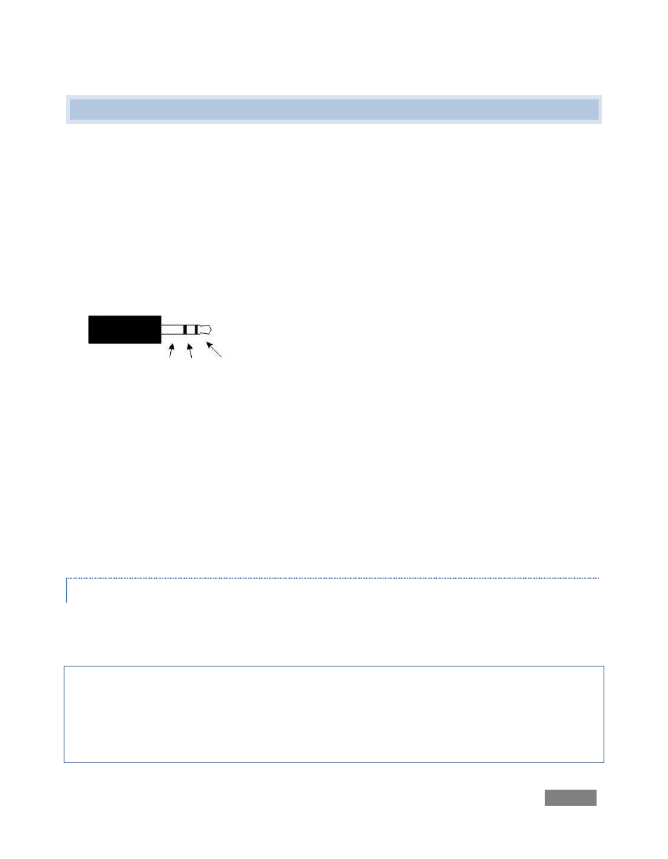
TriCaster’s tally light jacks employ standard TRS connectors (tip-ring-sleeve – see Figure 2) to
control external tally solutions, as described next:
The ‘ring’ connector provides a 'logic low' signal when the tally is not lit, and 'logic high' when it
is.
The signal is connected to the "ring" contact through a 100
ohm resistor.
The ‘sleeve’ contact is connected to ground through a 100 ohm resistor. This means there is a
total of 200 ohms resistance for current limiting when driving the diode. (This could be used to
drive a low-voltage solid state relay that would provide true isolated contact closure.)
An LED may be driven directly by connecting it across the ring and sleeve connections (no
external current limiting resistors needed). The LED anode should be connected to the ring and
cathode to the sleeve. Current is limited to 25mA (0.025 amps). When there is no load across the
ring and sleeve (and therefore no voltage drop across the current limiting resistors) you should
see a DC voltage of either 0 volts or about 4.5 volts, depending on whether the LED is off or on.
ENGINEERING NOTES
The tip and sleeve connections can be used to provide a sort of relay that closes when the tally
light is on (verify this with an ohm meter across the tip and sleeve connections).
Important Note: This is not a true contact closure circuit, since the sleeve (being tied to ground
through a 100 ohm resistor) it is not completely isolated. To prevent damage to TriCaster’s
components when making external connections to the tally light jacks, care should be taken that
connections to the sleeve are always at ground potential. Failure to do so could burn out the 100
ohm resistor, causing the LED tally feature to fail.
Figure 2