Omnia Audio Omnia.9/XE User Manual
Page 56
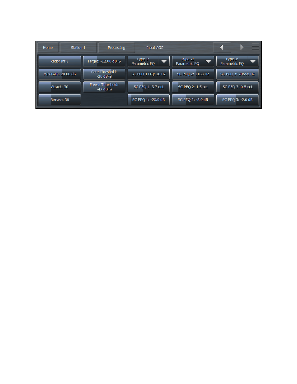
• The Ratio control determines how much the output audio will be increased or decreased in
relationship to the input audio of the Input AGC section. For example, a ratio of 3:1 means for every
3dB of change in the level of the input audio, the output will be changed by 1dB. Lower (looser)
settings provide less control of the dynamics in this section but provide a more open sound, while
higher (tighter) settings provide more control at the expense of openness. The range of this control
is 1.0:1 to Infinity:1.
• The Maximum Gain control works in conjunction with the Ratio control to determine how much
gain is available below threshold. If the Input AGC Ratio is set at Infinity:1 and the Input AGC
Maximum Gain is set to 36dB, the Input AGC has 36dB of range below threshold. At a ratio of 2.0:1
and the same Maximum gain setting, the range is reduced by half to 18dB. The scale to the left of
the Input AGC meter automatically adjusts as needed when changes are made to the Input AGC
Maximum Gain or the Input AGC Ratio to accurately reflect how much range is available below
threshold.
• The Attack control determines the speed with which the Input AGC acts to reduce audio above
threshold. Lower settings represent slower attack speeds and allow more audio to pass
unprocessed by the Input AGC into subsequent processing stages. Higher settings result in faster
attack speeds and allow less unprocessed audio to enter subsequent sections. Because all of
Omnia.9/XE’s processing stages are to some extent program-dependent, putting actual measures
of time on these controls would be pointless, and so the numbers on the various Attack and
Release controls throughout are simply relative numbers.
• The Release control determines the speed with which the Input AGC increases audio below
threshold. Lower settings provide slower release speeds, while higher settings result in faster
release speeds.
• The Target control sets the target output level of the Input AGC. A lower setting results in a lower
output level, while higher settings provide a higher output level. This is similar to a traditional
“threshold” control when the levels are below the target.
• The Gate Threshold and Freeze Threshold controls work together to determine the points at
which the release rate of the Input AGC slows by a factor of 3 (gate threshold) or freezes altogether
(freeze threshold). The range of these controls is -90dB to 0dB. Lower settings means the audio
must drop to a lower level before the release speed slows or freezes. Higher settings means the
audio doesn’t have to drop as much in level before the input AGC gain slows down or stops. Using
higher settings when employing faster Input AGC release speeds can keep the audio from being
increased too quickly or too much during quieter passages or pauses. If the display is sized and
configured in such a way that the Input AGC meter is shown vertically, a Gate condition will be
The Station Menu - Processing Menu
56