Installation & wiring, Sat & remote sat reset signal wiring, Sa e-bus controller technical guide – Orion System SA E-BUS Controller User Manual
Page 13: Space temperature sensor, Remote sat reset signal
SA E-BUS Controller Technical Guide
Installation & Wiring
13
GND
TMP
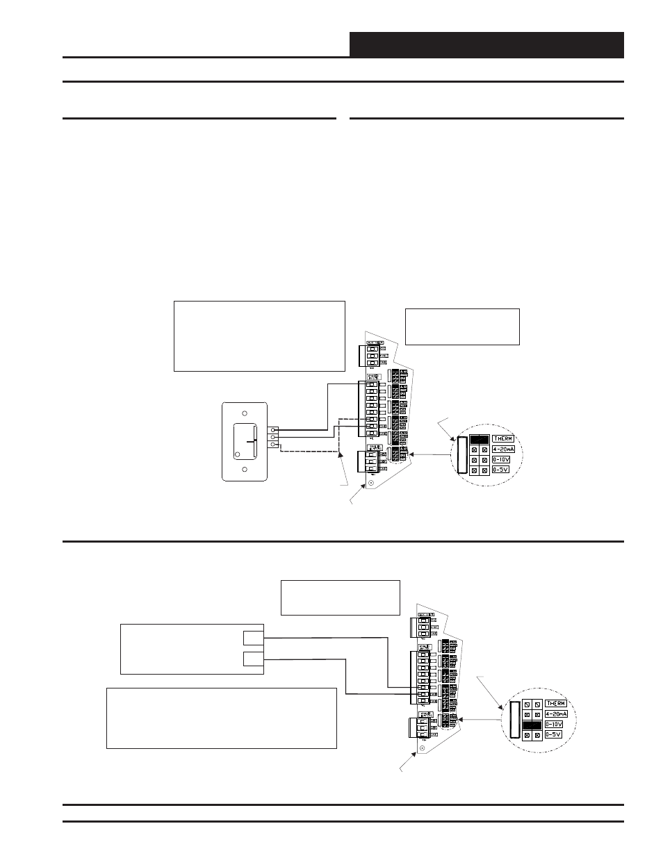
Space Temperature Sensor
OVR
R
E
L
O
C
R
E
M
R
O
A
W
AUX
Wire Required For
Sensors With Slide
Adjust Option Only
Set Jumper For THERM
When Space Sensor Slide
Adjust Is Wired To AI7
AI1
AI1 SET
AI2 SET
AI3 SET
AI4 SET
AI5 SET
AI7 SET
AI2
AI3
AI4
AI5
AI7
Note:
Either The Slide Offset Option For The Space
Temperature Sensor Or The Remote Supply
Air Temperature Reset Signal Option (By
Others) May Be Connected To An AI7 On
The SA E-BUS Controller. Only One Option
Is Allowed, Not Both.
AI1
AI7
GND
SA E-BUS Controller
Note: No Additional Wiring is
Required For Dual Cabinet
Units.
AI7 SET
Figure 8: Remote Supply Air Temperature Reset Signal Wiring
Space Temperature Sensor
The OE210, OE211, OE212, OE213 Space Temperature Sensor is typi-
cally used for constant volume HVAC unit applications controlling one
zone. The Space Temperature Sensor is a 10K Type III thermistor sensor
and should be mounted approximately 5 feet above the fl oor in the space
that is to be controlled. The Space Temperature Sensor is available as a
sensor only, sensor with override button, sensor with slide adjust, and
sensor with slide adjust and override confi gurations.
When the Remote Supply Air Temperature Reset Signal option is needed,
the Slide Offset option on the Room Sensor cannot be used. Only one
of these options may be used on the SA E-BUS Controller.
See Figure 7 below for complete Space Temperature Sensor wiring
details.
Remote Supply Air
Temperature Reset Signal
(By Others)
0-5 VDC or 0-10 VDC Signal
GND
Note:
Either The Slide Offset Option For The Space Temperature
Sensor Or The Remote Supply Air Temperature Reset
Signal Option (By Others) May Be Connected To AI7 On
The SA E-BUS Controller. Only One Option Is Allowed,
Not Both.
Regardless of Whether the Remote
SAT Reset Signal Has Been
Configured For 0-5 or 0-10 VDC,
Jumper Must Be Set For 0-10V
AI7
GND
SA E-BUS Controller
AI1
AI1 SET
AI2 SET
AI3 SET
AI4 SET
AI5 SET
AI7 SET
AI2
AI3
AI4
AI5
AI7
Note: No Additional Wiring
is Required For Dual Cabinet
Units.
AI7 SET
Figure 7: OE210, OE211, OE212, OE213 – Space Temperature Sensor Wiring
SAT & Remote SAT Reset Signal Wiring
Remote SAT Reset Signal
A Remote Supply Air Temperature Reset Signal can be connected to AI7
for applications requiring remote reset of the Supply Air Temperature
Setpoint.
When the Slide Offset option on the Room Sensor is used, the Remote
Supply Air Temperature Reset Signal cannot be used. Only one of these
options may be used on the SA E-BUS Controller.
The SA E-BUS Controller can accept either a 0-5 VDC signal or a 0-10
VDC signal on this input.
See Figure 8 below for complete Remote SAT Reset Signal wiring
details.