Appendix, Oe271 pressure sensor testing, Sa e-bus controller technical guide 62 – Orion System SA E-BUS Controller User Manual
Page 62
Zone
Zone
Appendix
SA E-BUS Controller Technical Guide
62
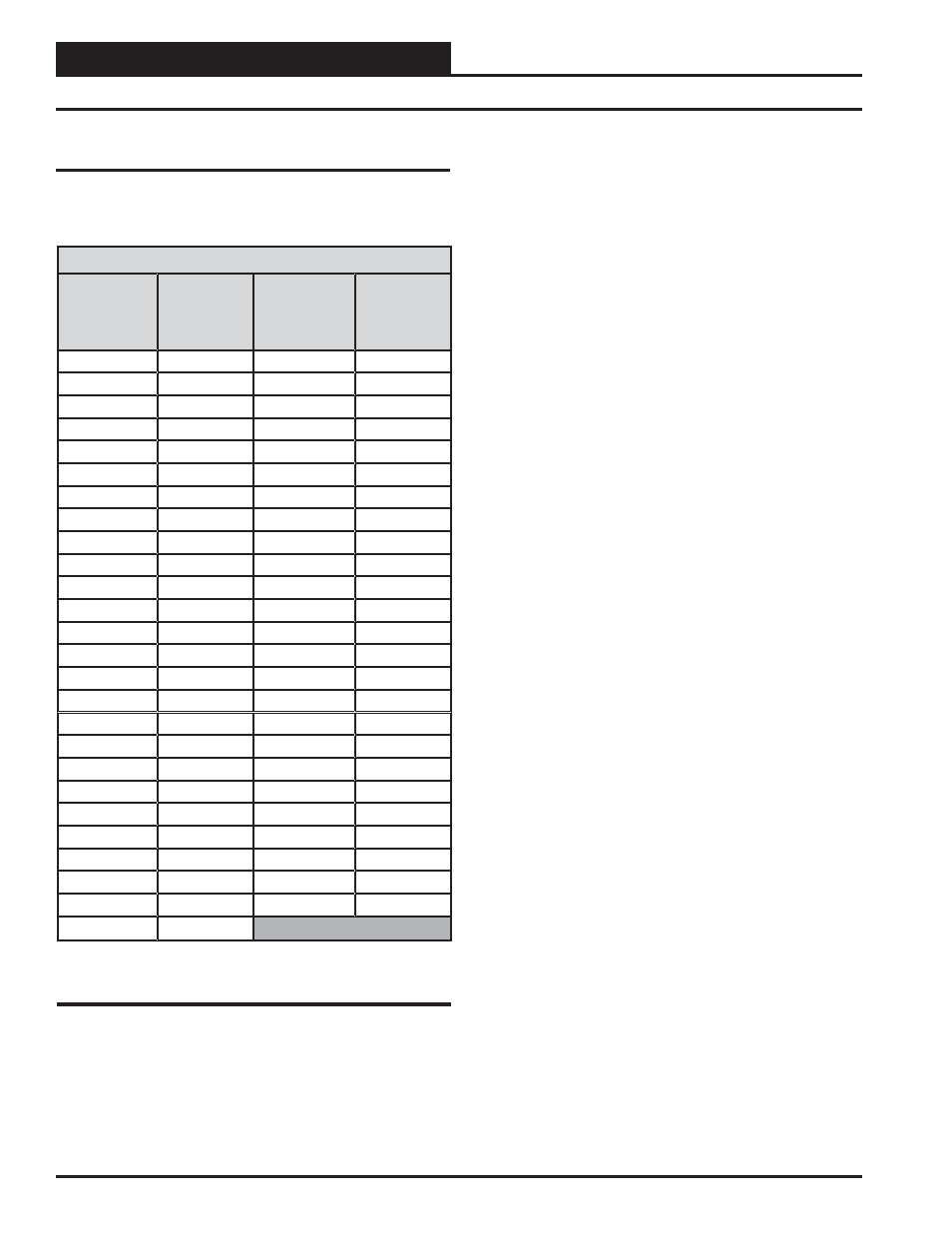
OE271 Pressure Sensor Testing Instructions
Use the voltage column to check the Duct Static Pressure Sensor while
connected to powered controllers. Read voltage with meter set on DC
volts. Place the “-” (minus) lead on the GND terminal and the “+” (plus)
lead on the 0-5 pin terminal on (TP) with the jumper removed. Be sure
to replace the jumper after checking.
OE271 Pressure Sensor Testing
OE271 Pressure Sensor Testing
The table below is used to troubleshoot the OE271 Duct Static Pressure
Sensors.
OE271 Duct Static Pressure Sensor
Pressure
@
Sensor
(“ W.C.)
Voltage
@
Input
(VDC)
Pressure
@
Sensor
(“ W.C.)
Voltage
@
Input
(VDC)
0.00
0.25
2.60
2.33
0.10
0.33
2.70
2.41
0.20
0.41
2.80
2.49
0.30
0.49
2.90
2.57
0.40
0.57
3.00
2.65
0.50
0.65
3.10
2.73
0.60
0.73
3.20
2.81
0.70
0.81
3.30
2.89
0.80
0.89
3.40
2.97
0.90
0.97
3.50
3.05
1.00
1.05
3.60
3.13
1.10
1.13
3.70
3.21
1.20
1.21
3.80
3.29
1.30
1.29
3.90
3.37
1.40
1.37
4.00
3.45
1.50
1.45
4.10
3.53
1.60
1.53
4.20
3.61
1.70
1.61
4.30
3.69
1.80
1.69
4.40
3.77
1.90
1.77
4.50
3.85
2.00
1.85
4.60
3.93
2.10
1.93
4.70
4.01
2.20
2.01
4.80
4.09
2.30
2.09
4.90
4.17
2.40
2.17
5.00
4.25
2.50
2.25
Table 6: Duct Static Pressure/Voltage for
OE271 Duct Static Pressure Sensors