Start-up & commissioning, Addressing & powering up, Sa e-bus controller technical guide 36 – Orion System SA E-BUS Controller User Manual
Page 36: Before applying power, Controller addressing, Power wiring, Zone, Sa e-bus controller
Zone
Zone
Start-Up & Commissioning
SA E-BUS Controller Technical Guide
36
Addressing & Powering Up
Before Applying Power
In order to have a trouble free start-up, it is important to follow a few
simple procedures. Before applying power for the fi rst time, it is very
important to correctly address the controller and run through a few
simple checks.
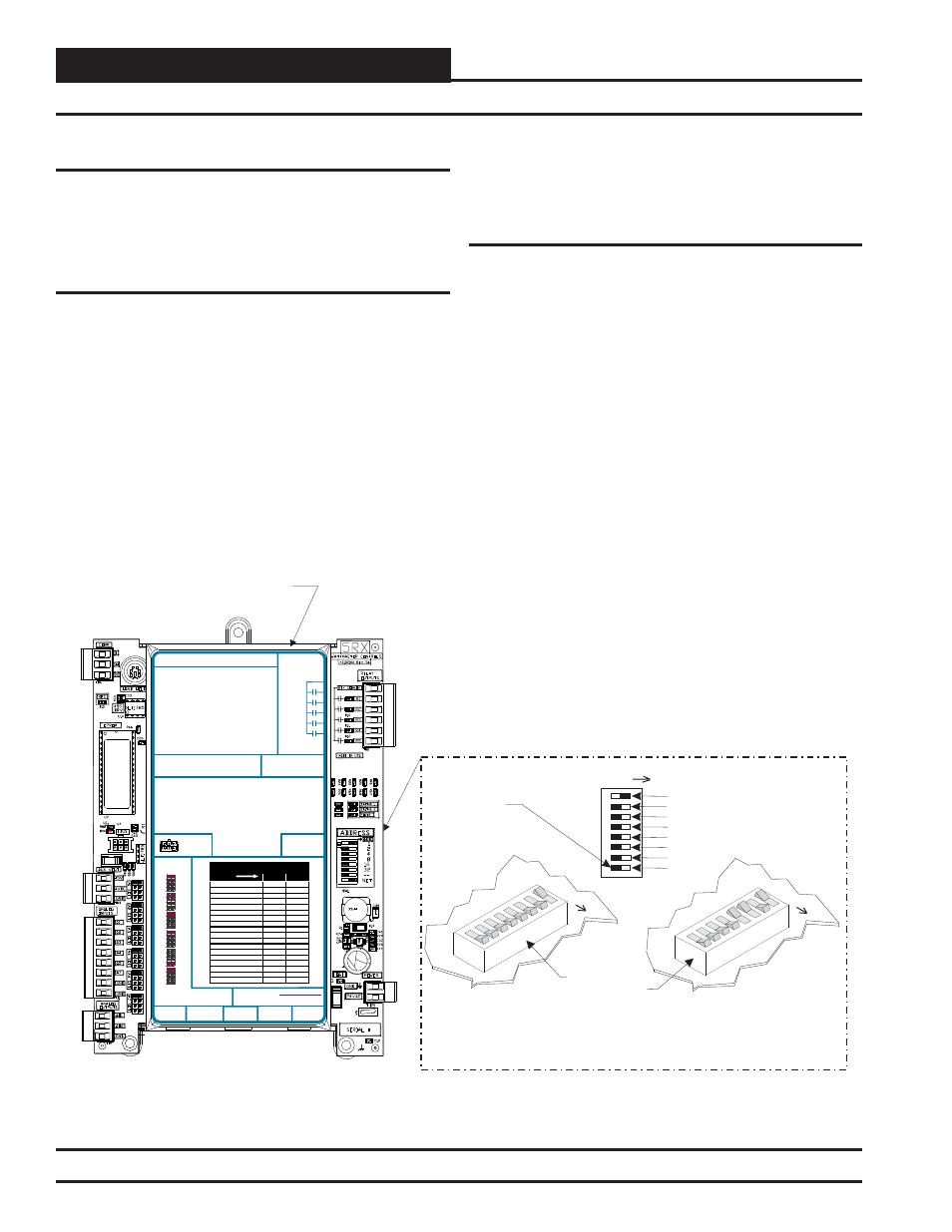
Controller Addressing
All SA E-BUS Controllers are equipped with address switches. If the SA
E-BUS Controller is to operate as a stand-alone system (not connected to
any other HVAC unit or VAV/Zone Controllers), the controller address
switch should be set for address 1. When using the Modular Service Tool
or System Manager to program and confi gure the SA E-BUS Control-
ler, you would enter this address to communicate with the controller.
When the system is to be connected to other HVAC unit controllers on
a communication loop, each controller’s address switch must be set with
a unique address between 1 and 59. When the SA E-BUS Controller
will be used with VAV/Zone Controllers, the SA E-BUS Controller’s
address switch must be set as address 59, no exceptions. See Figure 29
below for address switch setting information.
Power Wiring
One of the most important checks to make before powering up the
system for the fi rst time is to confi rm proper voltage and transformer
sizing for each controller. Each SA E-BUS Controller requires 8 VA of
power delivered to it at 24 VAC and each of the modules require differ-
ent VA loads (see Table 1 on page 10 for details). You may use separate
transformers for each device (preferred) or power several devices from a
common transformer. If several devices are to be powered from a single
transformer, correct polarity must be followed.
Figure 29: SA E-BUS Controller Address Switch Setting
SA E-BUS Controller
16
32
--------
NET
8
4
2
1
Address Switch Shown Is
Set For Address 1
Address Switch Shown Is
Set For Address 13
Controller
Address Switch
This Switch Should Be
In The OFF Position
As Shown
Note:
The Power To The Controller Must Be Removed And
Reconnected After Changing The Address Switch Settings In
Order For Any Changes To Take Effect.
Caution:
Disconnect All Communication Loop Wiring From The
Controller Before Removing Power From The Controller.
Reconnect Power And Then Reconnect Communication Loop
Wiring.
ADDRESS
ADD
ADD
ADD
The Address For Each Controller
Must Be Unique To The Other Controllers
On The Local Loop And Be Between 1 and 59
IC DIGITAL
SENSOR
2
IC
EXPANSION
2
STATIC
PRESSURE
LED BLINK CODES
LED NAME
STATUS1 STATUS2
NORMAL OPERATION
0
1
SAT FAIL
1
2
EAT FAIL
2
2
SPC FAIL
3
2
MECH COOL FAIL
1
3
MECH HEAT FAIL
2
3
FAN PROOF FAIL
3
3
DIRTY FILTER
4
3
WATER FLOW ALARM
6
3
DRAIN PAN ALARM
7
3
EMERGENCY SHUTDOWN
5
3
LOW SAT
1
4
HIGH SAT
2
4
CONT. TEMP COOL FAIL
3
4
CONT. TEMP HEAT FAIL
4
4
PUSH BUTTON OVR
1
5
ZONE OVR
2
5
OUTPUT FORCE ACTIVE
0
6
AI1 = SPC (SPACE TEMPERATURE SENSOR)
AI2
AI3
AI4
AI5
AI7
A01
A02
= SAT (SUPPLY AIR TEMPERATURE SENSOR)
= EWT (ENTERING WATER TEMPERATURE SENSOR)
= EAT (ENTERING AIR TEMPERATURE SENSOR)
= NOT USED
= SPACE TEMPERATURE SENSOR SLIDE ADJUST
OR VOLTAGE RESET SOURCE
= WATER SIDE ECONOMIZER VALVE 1A &1B (2-10 VDC)
= SUPPLY FAN VFD (0-10 VDC OUTPUT)
ANALOG INPUT JUMPER SETTINGS
MUST BE SET AS SHOWN FOR
PROPER OPERATION
24 VAC POWER ONLY
WARNING! POLARITY MUST BE OBSERVED
OR THE CONTROLLER WILL BE DAMAGED
AI1
AI2
AI3
AI4
THERM
THERM
THERM
THERM
THERM
THERM
4-20mA
4-20mA
4-20mA
4-20mA
4-20mA
4-20mA
0-10V
0-10V
0-10V
0-10V
0-10V
0-10V
0-5V
0-5V
0-5V
0-5V
0-5V
0-5V
AI5
AI7
ANALOG INPUT
JUMPER
SETTINGS
E-BUS
CONNECTOR
WattMaster Label
#LB102060-01-A
Rev.: 1A
RELAY CONTACT
RATING IS 1 AMP
MAX @ 24 VAC
RS-485 COMMUNICATION LOOP. WIRE
“R” TO “R”, “T” TO “T” “SHLD” TO “SHLD”
FAN
RELAY 2
RELAY 3
RELAY 4
RELAY 5
RELAY
COMMON
SA
CONTROLLER
E-BUS
Orion No.:OE332-23E-VCMX-SA
AAON No.:
V07160