Inputs & outputs, Sa expansion module binary inputs, Sa e-bus controller technical guide 40 – Orion System SA E-BUS Controller User Manual
Page 40
Zone
Zone
Inputs & Outputs
SA E-BUS Controller Technical Guide
40
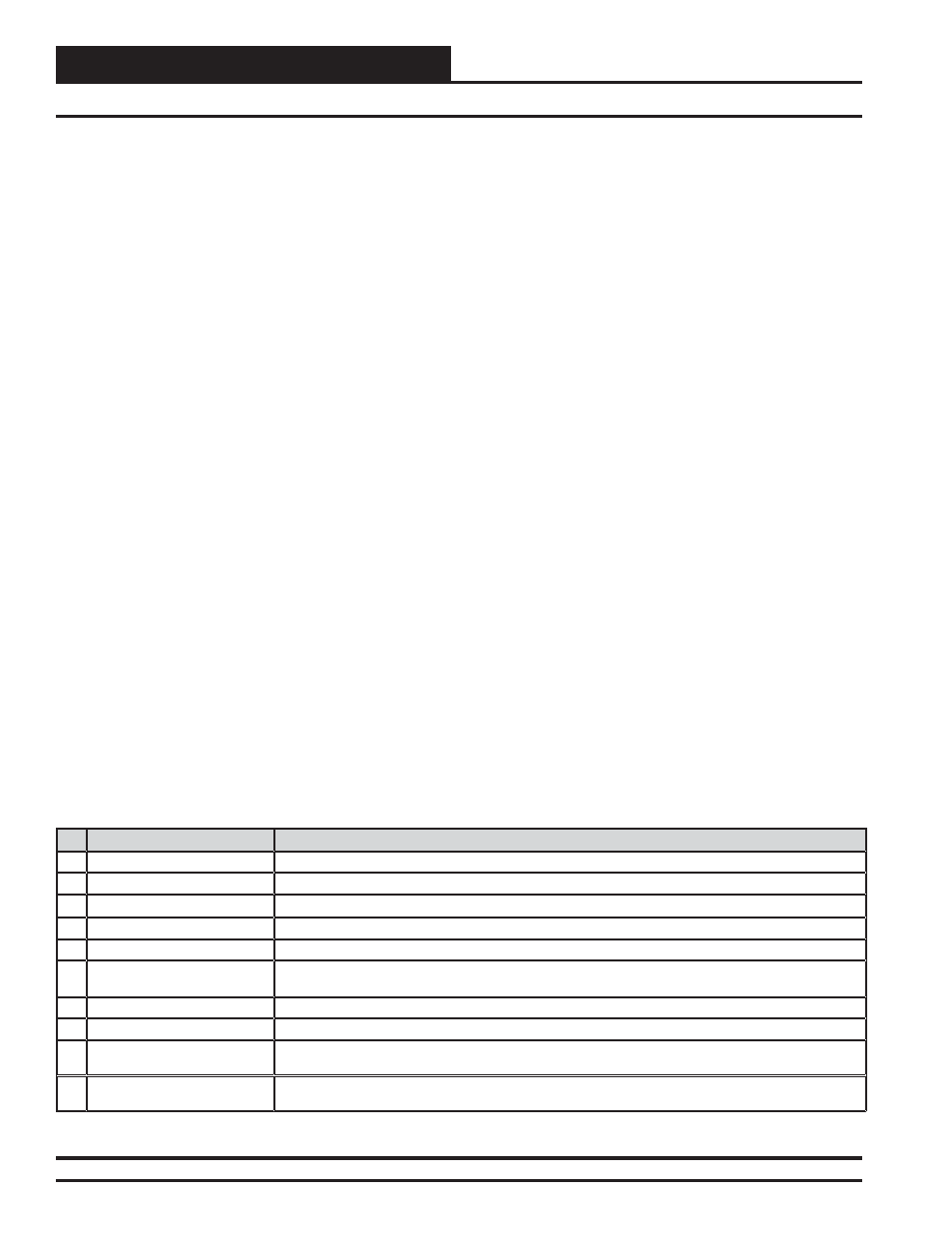
R1-R4 - User-Confi gurable Relay Outputs
Confi gure relays as indicated by the factory wiring diagram when
mounted controls are used. The options are listed in Table 2 below.
BI1 - Water Proof of Flow Input A
This input is for the Water Proof of Flow Switch for a single SA Unit or
for Unit A of a Dual SA Unit. If the Water Proof of Flow Switch contact
opens while the Condenser Valve is operating, the Unit will enter Water
Proof of Flow Failure mode. In this mode, the mechanical cooling will
deactivate and the Condenser Valve will be forced to 100%. The Unit
will exit this mode when the Water fl ow Switch is closed again and
Water Flow is proven.
BI2 - Water Proof of Flow Input B
This input is for the Water Proof of Flow Switch for Unit B of a Dual
SA Unit. If the Water Proof of Flow Switch contact opens while the
Condenser Valve is operating, the Unit will enter Water Proof of Flow
Failure mode. In this mode, the mechanical cooling will deactivate and
the Condenser Valve will be forced to 100%. The Unit will exit this
mode when the Water fl ow Switch is closed again and Water Flow is
proven.
BI3 - Air Proof of Flow Input
An Air Proof of Flow Switch that provides a wet contact closure when-
ever the HVAC Unit Supply Fan is operating can be connected to this
input. If the Air Proof of Flow Switch contact opens while the Supply
Fan is operating, all Heating and Cooling is suspended or disabled.
The Air Proof of Flow Switch is an optional input. This means that you
must confi gure the SA E-BUS Controller to recognize this input signal.
BI4 - Remote Forced Occupied Mode Input
When this wet contact input closes, it will force the SA E-BUS Con-
troller into the Occupied Mode. When the Remote Forced Occupied
Signal is removed, the controller will revert to the Unoccupied Mode
of operation if no internal or external schedule has been confi gured or
is in effect when this occurs.
BI5 - Emergency Shutdown Input
This wet contact input is used to initiate shutdown of the HVAC Unit
when an N.C. Smoke Detector (by others), Firestat (by others), or other
shutdown condition (by others) contact is opened. The controller remains
active and can initiate alarm relays.
BI6 - Drain Pan Overfl ow Input A
This input is for the Drain Pan Overfl ow Switch for a single SA Unit
or for Unit A of a Dual SA Unit. When the drain pan is in an overfl ow
condition, a Drain Pan Overfl ow Switch will provide a 24 VAC wet
contact closure to this input. When this contact closure is initiated, the
controller will enter Drain Pan Overfl ow Failure Mode and deactivate
mechanical cooling.
BI7 - Drain Pan Overfl ow Input B
This input is for the Drain Pan Overfl ow Switch for Unit B of a Dual
SA Unit. When the drain pan is in an overfl ow condition, a Drain Pan
Overfl ow Switch will provide a 24 VAC wet contact closure to this
input. When this contact closure is initiated, the controller will enter
Drain Pan Overfl ow Failure Mode and deactivate mechanical cooling.
BI8 - Dirty Filter Contact Closure Input
This wet contact input is required for Filter Status Indication and requires
a Differential Pressure Switch to initiate “Dirty Filter” indication.
SA Expansion Module Binary Inputs
Table 2: User-Confi gurable Relay Outputs
No.
Relay Description
Details
1
Heating Stages
Confi gure (1) Relay for each stage of heat. Confi gure (1) Relay for Mod heat.
2
Cooling Stages
Confi gure (1) Relay for each stage of cooling. For Chilled Water, confi gure (1) Relay for cooling.
3
Warm-Up Mode (VAV Boxes)
Confi gure (1) Relay for Warm-Up Mode when Non-Orion VAV/Zone Controllers are used.
4
Reversing Valve (Heat Pumps) Confi gure (1) Relay for Reversing Valve operation. Can be confi gured for heating or cooling.
5
Reheat (Dehumidifi cation)
Confi gure (1) Relay for On/Off reheat when used.
6
Pre-Heater
(low ambient protection)
Confi gure (1) Relay for pre-heat coil when required. Activated when the Entering Air Temperature
drops below the Ambient Protection Setpoint.
7
Alarm
Confi gure (1) Relay to initiate an alarm output when any SA E-BUS Controller alarm occurs.
8
Override
Confi gure (1) Relay to initiate an output signal when Space Temperature override button is pushed.
9
Occupied
Confi gure (1) Relay to initiate an output signal any time the SA E-BUS Controller is in Occupied
Mode.
10
Water Side Economizer
Confi gure (1) Relay to initiate an output signal any time the SA E-BUS Controller is in Economizer
Mode.