Installation & wiring, Water side economizer wiring, Sa e-bus controller technical guide – Orion System SA E-BUS Controller User Manual
Page 17: Water side economizer (wse) valve(s), Water side economizer (wse) bypass valve, Figure 12: water side economizer valve wiring
SA E-BUS Controller Technical Guide
Installation & Wiring
17
Water Side Economizer Wiring
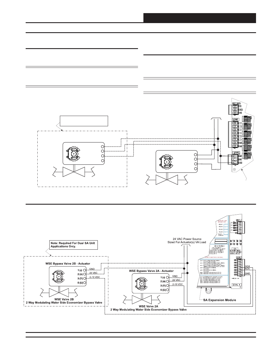
Water Side Economizer (WSE) Valve(s)
The Water Side Economizer Valve(s) must be wired as shown in Figure
12 below for proper operation of the SA E-BUS Controller. The Water
Side Economizer Valve(s) connects to AO1 on the SA E-BUS Controller.
NOTE: For Dual Cabinet Units, wire the Second Cabinet’s WSE
Valve Actuator in parallel with the First Cabinet’s WSE Valve
Actuator.
Figure 12: Water Side Economizer Valve Wiring
WSE Valve 1A - Actuator
WSE Valve 1B - Actuator
WSE Valve 1A
2 Way Modulating Water Side Economizer Valve
Note: Required For Dual SA Unit
Applications Only.
WSE Valve 1B
2 Way Modulating Water Side Economizer Valve
2-10 VDC
2-10 VDC
24 VAC Power Source
Sized For Actuator(s) VA Load
GND
GND
24 VAC
24 VAC
3 (Y)
3 (Y)
5 (U)
5 (U)
2 (+)
2 (+)
1 (-)
1 (-)
SA E-BUS Controller
GND
AO1
AI1
AI1 SET
AI2 SET
AI3 SET
AI4 SET
AI5 SET
AI7 SET
AI2
AI3
AI4
AI5
AI7
Figure 13: Water Side Economizer Bypass Valve Wiring
Water Side Economizer (WSE) Bypass
Valve
The Water Side Economizer Bypass Valve(s) must be wired as shown in
Figure 13 below for proper operation of the SA E-BUS Controller. The
Water Side Economizer Bypass Valve(s) are wired to AO4 and AO5 on
the SA Expansion Module.
NOTE: For Dual Cabinet Units, wire the Second Cabinet’s WSE
Bypass Valve Actuator to AO5 on the SA Expansion Module.