Start-up & commissioning, Sa e-bus controller technical guide, Initialization – Orion System SA E-BUS Controller User Manual
Page 37: Operating summary, Programming the controller, Modular service tool, Modular system manager
SA E-BUS Controller Technical Guide
Start-Up & Commissioning
37
Warning: Observe Polarity! All boards must be wired with
GND-to-GND and 24 VAC-to-24 VAC. Failure to observe
polarity will result in damage to one or more of the boards.
The Expansion Module must be wired in such a way that the
Expansion Module and the SA E-BUS Controller are always
powered together. Loss of power to the Expansion Module
will cause it to become inoperative until power is restored
to the Expansion Module.
Check all wiring leads at the terminal block for tightness. Be sure that wire
strands do not stick out and touch adjacent terminals. Confi rm that all sen-
sors required for your system are mounted in the appropriate location and
wired into the correct terminals on the SA E-BUS Controller. Be sure any
Expansion Module connected to the SA E-BUS Controller is also cor-
rectly wired just as you did for the SA E-BUS Controller.
After all the above wiring checks are complete, apply power to the SA
E-BUS Controller and any Expansion Module connected to it.
Initialization
On system power up, a 30-second startup delay is performed where all
default setpoints are initialized, LED’s are initialized, and all outputs
are turned off.
When power is fi rst applied, LED1 and LED2 will fl ash out the controller
address. LED1 will fl ash to represent the tens position. LED2 will fl ash
to represent the ones position. After the controller address is complete,
there will be a short pause and then 60 fast fl ashes to represent controller
initialization. There will be no controller operation or communications
during initialization. After initialization, LED1 and LED2 will continu-
ously fl ash the status code.
Example of a controller address of 59:
LED1 will fl ash 5 times. LED2 will fl ash 9 times.
See Table 3 on page 55 in the Troubleshooting Section of this manual
for detailed diagnostic blink code information.
Operating Summary
There is a standard set of operating instructions that are continuously
repeated during normal operations. They are listed below.
1. Read Analog Inputs for Temperatures, Pressures, and
Binary Contact Closures.
2. Calculate Occupied/Unoccupied Mode of Operation.
3. Calculate HVAC Mode of Operation.
4. Set all outputs to match calculations for Heating or Cooling
or
Vent
Mode.
5. Broadcast information to other controllers if confi gured.
6. Log all temperatures and output conditions.
7.
Repeat steps 1 through 6 continuously.
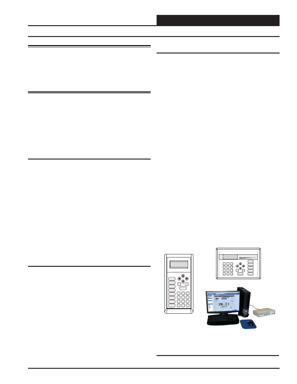
Programming the Controller
The next step is programming the controller for your specifi c require-
ments. In order to confi gure and program the SA E-BUS Controller, you
must use an operator interface. Three different operator interfaces are
available for programming and monitoring of the SA E-BUS Controller.
These are as follows:
•
Modular Service Tool
•
Modular System Manager
•
Computer with Prism 2 Computer Front-End Software
Installed
Any of these devices or a combination of them can be used to access
the status, confi guration, and setpoints of any controller on your com-
munications loop.
If using the Modular Service Tool or Modular System Manager with your
system, refer to the SA E-BUS Controller Operator Interfaces Technical
Guide for complete SA E-BUS Controller programming instructions.
If using a Notebook or Desktop computer and the Prism Computer Front
End Software, refer to the Prism 2 Technical Guide.
No matter which operator interface you use, we recommend that you
proceed with the programming and setup of the SA E-BUS Controller
in the order that follows:
1.
Confi gure the Controller for your application.
2.
Program the Controller setpoints.
3.
Program the Controller operation schedules.
4.
Set the Controller current time and date.
5.
Review Controller status screens to verify system
operation and correct Controller confi guration.,
Programming the Controller
Figure 30: Modular Service Tool, Modular System
Manager, and Prism 2 Operator Interfaces
ENTER
CLEAR
ESC
PREV
NEXT
DOWN
UP
6
5
4
DEC
7
0
8
1
3
2
9
MINUS
-
STATUS
SETPOINTS
SCHEDULES
ALARMS
OVERRIDES
System Manager
Mode
Selection
ENTER
CLEAR
ESC
PREV
NEXT
DOWN
UP
6
5
4
DEC
7
0
8
1
3
2
9
MINUS
-
STATUS
SETPOINTS
SCHEDULES
CONFIGURATION
ALARMS
ON
OVERRIDES
BALANCE - TEST