Installation – REMKO KWL 130 H User Manual
Page 21
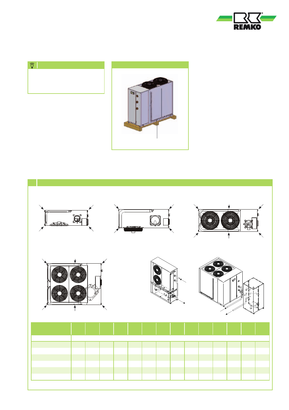
Installation
NOTE
Transport packaging
Transport pallet
Unit layout
KWL
130
KWL
160
KWL
180
KWL
220
KWL
270
KWL
320
KWL
370
KWL
130H
KWL
160H
KWL
180H
KWL
220H
KWL
270H
KWL
320H
KWL
370H
Holediameter
13 mm
Load point A
40
41
58
62
46
48
58
41
43
61
65
48
49
61
Load point B
40
41
68
72
51
54
61
42
43
71
76
54
55
64
Load point C
40
41
60
61
56
58
69
41
43
64
64
59
61
72
Load point D
44
44
69
75
48
50
56
46
47
72
80
51
51
59
Load point E
-
-
-
-
53
55
64
-
-
-
-
55
56
67
Load point F
-
-
-
-
55
59
72
-
-
-
-
58
60
75
6 Weight loads
All values in kg
KWL 130(H) - 160(H)
KWL 180(H) - 220(H)
KWL 270(H) - 320(H)
KWL 370 (H)
KWL (H) with medium storage tank
A
C
B
D
A
C
E
F
B
D
A
C
E
F
B
D
A
C
B
D
Installation may only be
undertaken by authorised
personnel.
Separating the
Transport pallet
The system is supplied with a pallet
for the purpose of transportation.
Remove this before installation.
Unit installation
1. Install the vibration absorbers
(accessories) under the system
(Figure 6
).
2. Attach the unit to the building
where structurally permitted.
3. Ensure that structure-borne
noise is not transferred to other
parts of the building.
4. Connect the medium lines.
21