Remko kwl (h), Electrical connection – REMKO KWL 130 H User Manual
Page 26
Electrical connection
■
All electrical connections such
as network supply, cable remote
control etc. must be carried out
in the unit's switch cabinet.
■
The lines to be installed are to
be pulled into the switch cabi-
net through the cable conduits.
■
An electrician must determine
the sizing and selection of the
fuses and the cross section of
the the lines to be installed.
Note that starting current may
be up to 10 times nominal cur-
rent.
The following electrical connec-
tions must be provided:
■
Connection to the power supply.
■
Possible enabling contact for
the set mode or stand-by.
■
Possible operating mode
contact for cooling or heating
mode (units with HP-function)
■
Possible connection of a winter
pressure controller (accessory)
■
Possible connection of crank
case heating (accessory).
■
Possible connection of a cable
remote control
(accessories).
■
Possible connection of anti-
freeze protection heating me-
dium (accessory, factory instal-
lation only).
Power supply
The unit requires a fixed three
phase alternating current connec-
tion. The mains connection is to be
connected to the L1, L2, L3, N and
PE terminals.
All electrical installation work
is to be performed by specialty
companies. Disconnect the
voltage supply when connect-
ing the electrical terminals.
!
CAUTION
■
The power supply is made at
the chiller; a control cable to
the interior unit is not neces-
sary.
■
An all pole separating switch,
which activates individual phase
conductors in the event of
a malfunction, must be installed
in the supply line upstream
from the unit.
■
Electric connections must be
carried out as fixed connections
in accordance with the applica-
ble regulations.
■
Check all terminal points for
stability.
■
The supply line must be ad-
equately insulated on-site
and the voltage drop may not
exceed permissible values.
■
Make sure that the electri-
cal system is adequate for the
operation of the unit and and
can supply the operating cur-
rent necessary for other already
operated units.
■
Determine before installation,
when connecting to existing
system components, whether
the unit's service connection is
adequately sized for the unit's
rated input.
■
The connection of the units
must always be carried out with
adequately sized, low-resistance
protective earthing conductors
and if necessary more than
once (especially with plastic
tubing).
■
When installing the units on
flat roofs, lightning protection
measures may be necessary.
We recommend the use of safety
fuses.
NOTE
Check all plugged and
clamped terminals to verify
they are seated correctly and
make a permanent contact.
Tighten as required.
!
CAUTION
External enabling contact
Operating mode / Stand-By
In addition to being operated with
the controller or the cable remote
control, the unit can be switched
on (normal mode) and switched
off (Stand-By) over an external po-
tential free contact (programmable
as opener or closer) (Figure 7).
The controller must be configured
if a closer is used for the external
enabling.
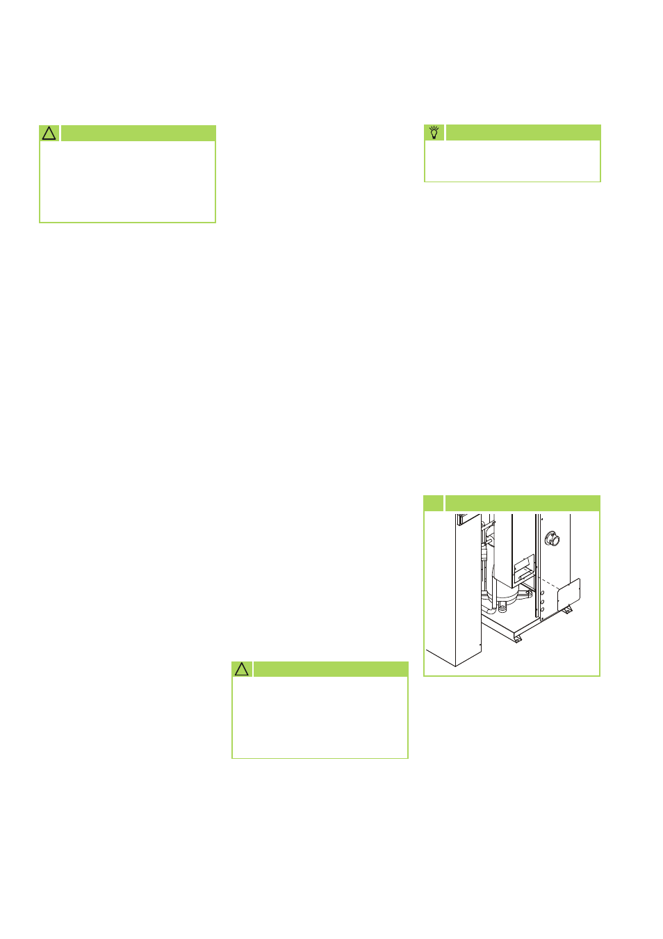
7 Terminal connections
Please proceed as follows to con-
nect:
1. Open the control panel and
switch cabinet cover by
removing the screws and
lifting off the cover.
2. Feed the voltage-free cable
through the conduits into the
switch cabinet and clamp the
cable to the strain relief.
3. Then connect the cable in ac-
cordance with the connection
diagram.
4. Ensure a correct rotating field.
5. Reinstall all parts which were
removed.
REMKO KWL (H)
26