Sundance SMT702 User Manual
Page 44
4.3.1.2.19
Frequency Synthesizer (LMX2531) Register R1 – 0xC4
(write and read).
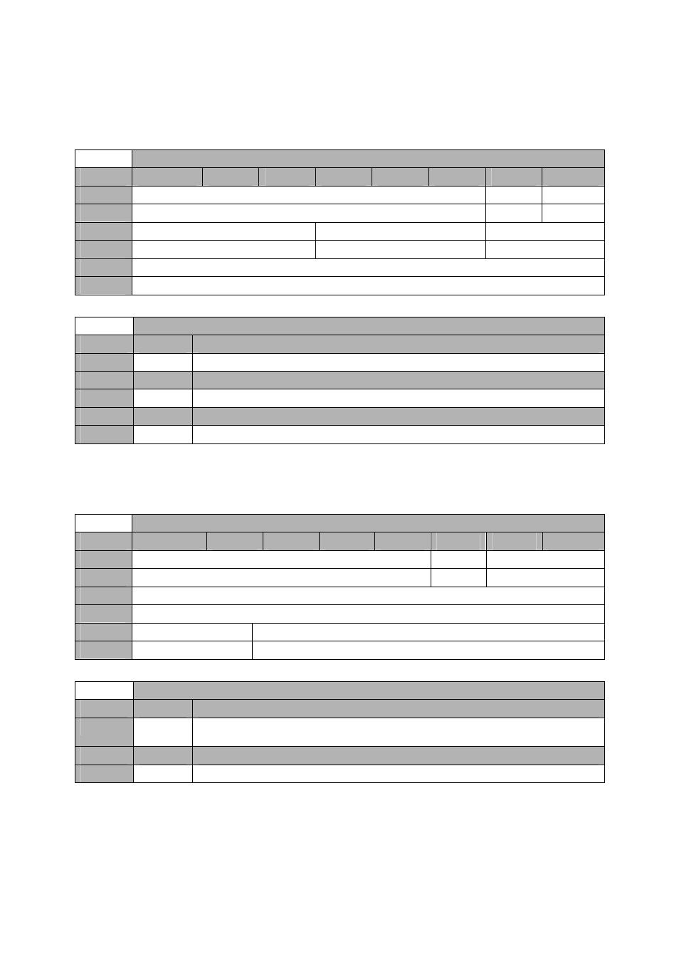
Offset 0x0400 -
Frequency Synthesizer (LMX2531) Register R1 – 0xC4 (write and read)
Byte
Bit 7
Bit 6
Bit 5
Bit 4
Bit 3
Bit 2
Bit 1
Bit 0
2
Reserved
Reserved
ICP[4]
Default
‘000000’
‘1’
‘0’
1
ICP[3:0]
N[10:8]
NUM[21:20]
Default
‘000’
‘000’
‘00’
0
NUM[19:12]
Default
‘00000000’
Offset 0x0400 -
Frequency Synthesizer (LMX2531) Register R1 – 0xC4 (write and read)
Setting
Bit 9-0
Fractional numerator (NUM[21:12])
0
0
Value between 0 (all 0s) and 4194303 (all 1s)
Setting
Bit 12-10
N Counter (N[10:8])
0
0
Value between 0 (0x37) and 2039 (0x3F7)
Setting
Bit 16-13
Charge Pump Current (ICP[4:0])
0
0
0x0 corresponds to 90uA (state 1x) and 0xF (State 16x) to 1440uA (90uA per state)
4.3.1.2.20
Frequency Synthesizer (LMX2531) Register R2 – 0xC8
(write and read).
Offset 0x0400 -
Frequency Synthesizer (LMX2531) Register R2 – 0xC8 (write and read)
Byte
Bit 7
Bit 6
Bit 5
Bit 4
Bit 3
Bit 2
Bit 1
Bit 0
2
Reserved
Reserved
DEN[11:0]
Default
‘00000’
‘1’
‘00’
1
DEN[11:0]
Default
‘00000000’
0
DEN[11:0]
R[5:0]
Default
‘00’
‘000000’
Offset 0x0400 -
Frequency Synthesizer (LMX2531) Register R2 – 0xC8 (write and read)
Setting
Bit 5-0
R Counter Value (R[5:0])
0
0
R Country Value – These bits determine the phase detector frequency. Only possible
values are 1, 2, 4, 8, 16 or 32
Setting
Bit 17-6
Fractional Denominator DEN[11:0]
0
0
Value between 0 (all 0s) and 4194303 (all 1s)