Super Systems X5 User Manual
Page 12
12
3 - Electrical Connections
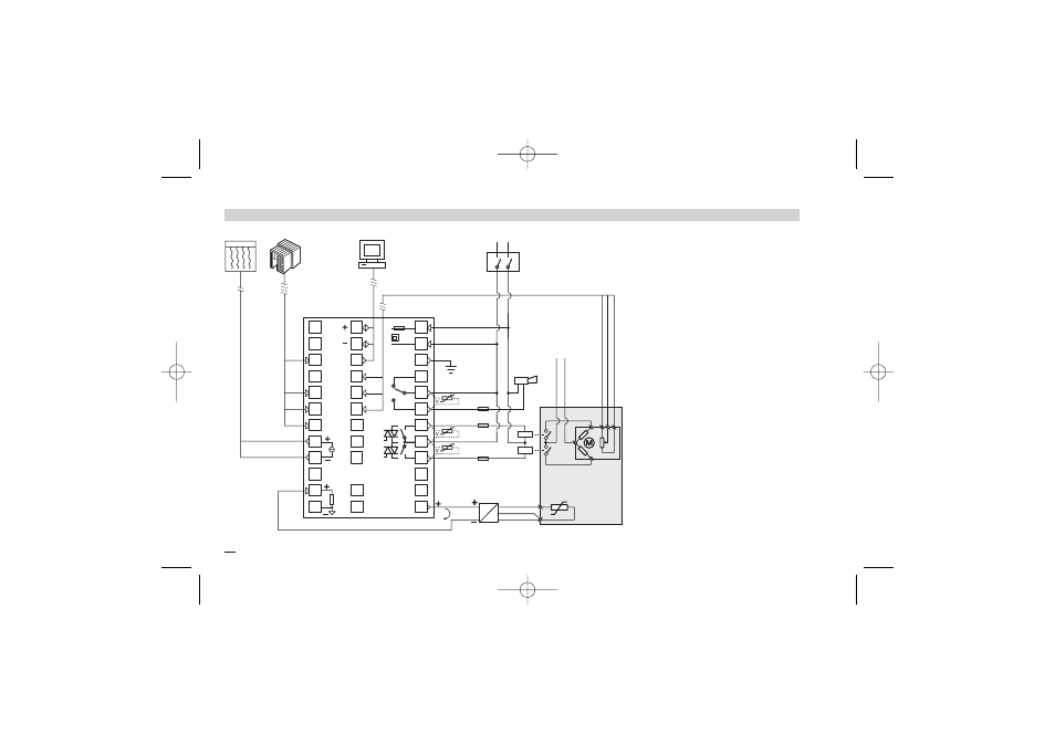
3.3 EXAMPLE OF WIRING DIAGRAM (VALVE CONTROL)
B
Notes:
1] Ensure that the power supply voltage is
the same as that on the instrument label.
2] Switch ON the power supply only after
all electrical connections have been
completed.
3] In accordance with electrical safety reg-
ulations, there must be an easly identifi-
able and accessable power disconnect.
4] The instrument is PTC protected.
In case of failure, return the instrument to
the manufacturer for repair.
5] To protect internal circuits use:
- 2 A
~
T fuse for Relay outputs (220 Vac)
- 4 A
~
T fuse for Relay outputs (110 Vac)
- 1 A
~
T fuse for Triac outputs
6] Relay contacts are protected with varis-
tors.
In case of 24 Vac inductive loads, use
model A51-065-30D7 varistors (on
request).
Supervisory
Commands
RS485
Power
supply
switch
Alarm
V
~
[3]
C
IL1
IL2
IL3
[6]
[6]
[5]
[5]
[5]
OP3
OP1
OP2
°C
C
Retransm.
I
Pt100
[6]
Transmitter
4…20mA
24V
V
~
Servomotor
Rj
PTC
12
11
10
9
8
7
6
5
4
3
2
1
24
23
20
19
36
35
34
33
32
31
30
29
28
27
26
25
18
17
16
15
14
13
21
X5-SSI-uk 18-03-2009 17:53 Pagina 12